
Tilting device for a chair

A tilting device and chair technology, applied in chairs, recliners, applications, etc., can solve the problems of expensive and complicated structures

Inactive Publication Date: 2013-04-03
TOPSTAR
View PDF7 Cites 0 Cited by
  • Summary
  • Abstract
  • Description
  • Claims
  • Application Information

AI Technical Summary

Problems solved by technology

[0003] A disadvantage in the known tipping devices for chairs is that the construction with a large number of parts is generally very expensive and complicated

Method used


Image

  • Tilting device for a chair
  • Tilting device for a chair
  • Tilting device for a chair

Examples


Embodiment Construction

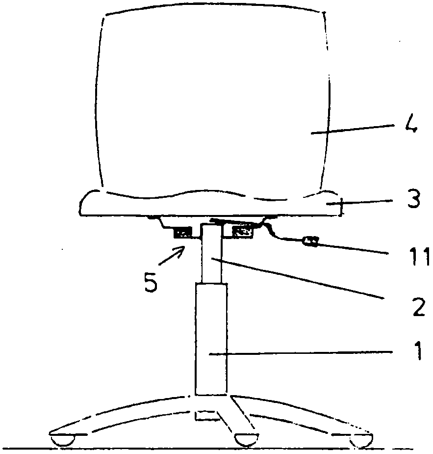
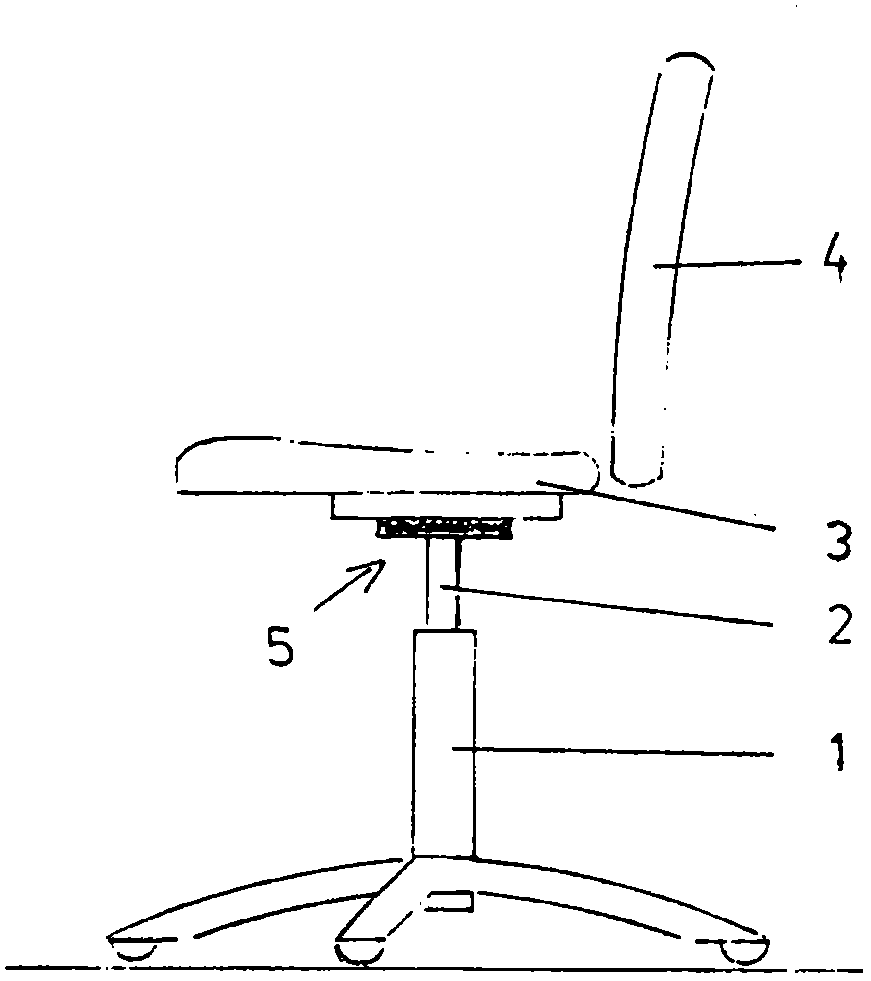
[0016] exist Figure 1a and 1b The chair shown in has a chassis 1 . The base frame 1 has a gas spring 2 extending vertically upwards thereto.

[0017] Furthermore, the chair has a seat 3 . A backrest 4 is arranged next to the seat.

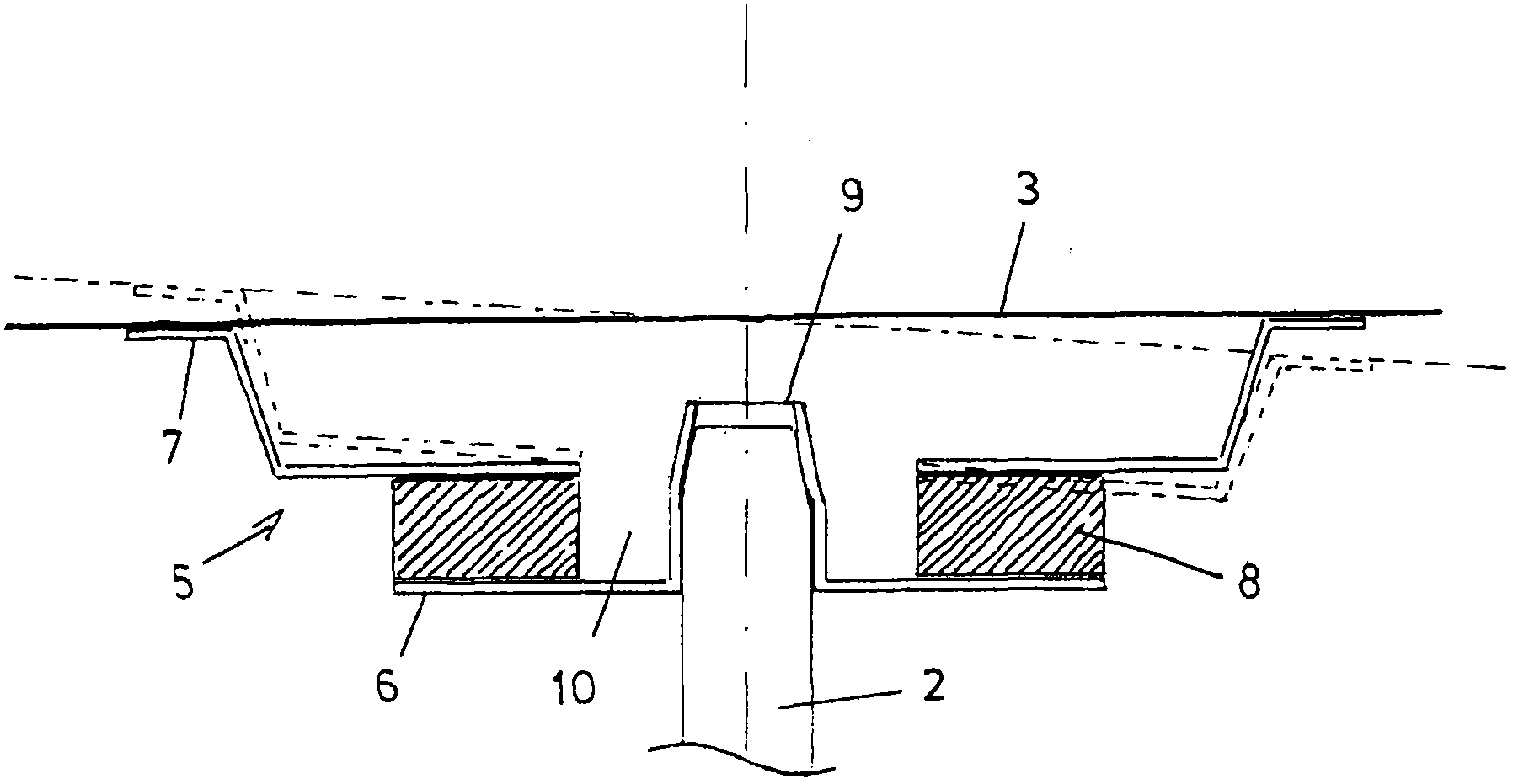
[0018] A tipping device 5 is arranged between the chassis 1 and the seat 3 . The tilting device 5 comprises a lower plate 6 , an upper plate 7 and an elastic body 8 interposed therebetween.

[0019] The lower plate 6 has a bulge 9 protruding vertically upward along the central axis. In the exemplary embodiment, the bead is initially cylindrical and then tapers conically toward the top. The upper plate 7 is arranged at a distance above the lower plate 6 . The elastic body 8 is in between. The elastomer is connected to the two plates 6, 7 by vulcanization. However, the elastomer can also be glued, riveted or screwed to the two plates 6 , 7 . It is also conceivable to fix by means of a positive fit, for example with barbs or a snap connectio...


PUM


Abstract

The invention relates to a tilting device (5) for a chair, comprising a lower plate (6) and an upper plate (7). An elastic body (8) is located therebetween. The lower plate (6) has a bulge (9) in the vertical direction, by means of which the tilting device (5) is placed onto the upper end of a gas spring (2). The seat plate (3) of the chair is fastened to the upper plate (7).

Description

technical field [0001] The invention relates to a tilting device for a chair according to the preamble of claim 1 . Background technique [0002] Chairs are known in various embodiments which enable a tilting movement of the seat about a fulcrum located in the region of the central seat. The basic principle is always to provide a support on the underside of the seat using elastomers. Such an elastomer resists the tilting movement with a corresponding restoring force. [0003] A disadvantage of the known tipping devices for chairs is that the overall construction with a large number of parts is very expensive and complicated. Contents of the invention [0004] Proceeding from this, the object of the invention is to provide a technically simple tilting device for chairs. [0005] This solution is characterized by what is stated in the characterizing part of claim 1 . [0006] This provides a tilting device for chairs which is technically extremely simple and consists ove...

Claims


Application Information

Patent Timeline
Patent Type & Authority Applications(China)
IPC IPC(8): A47C3/025A47C7/14A47C3/026
CPCA47C7/14A47C1/03255A47C3/0252A47C7/448A47C3/026
Inventor S·迈尔P·瓦格纳
Owner TOPSTAR
Learn More