Thread laying drive, especially for working station of textile machine

A motor drive, drive technology, applied in the direction of thin material handling, delivery of filamentous materials, transportation and packaging, etc., can solve problems such as unresolved

Inactive Publication Date: 2008-05-07
SAURER GERMANY GMBH & CO KG
View PDF2 Cites 0 Cited by
  • Summary
  • Abstract
  • Description
  • Claims
  • Application Information

AI Technical Summary

Problems solved by technology

Although the actual angular position of the yarn guide can be determined quickly and accurately with the disclosed angular sensors, the above-mentioned problems of the previously used open-loop or closed-loop control systems have not been solved

Method used


Image

  • Thread laying drive, especially for working station of textile machine

Examples


Embodiment Construction

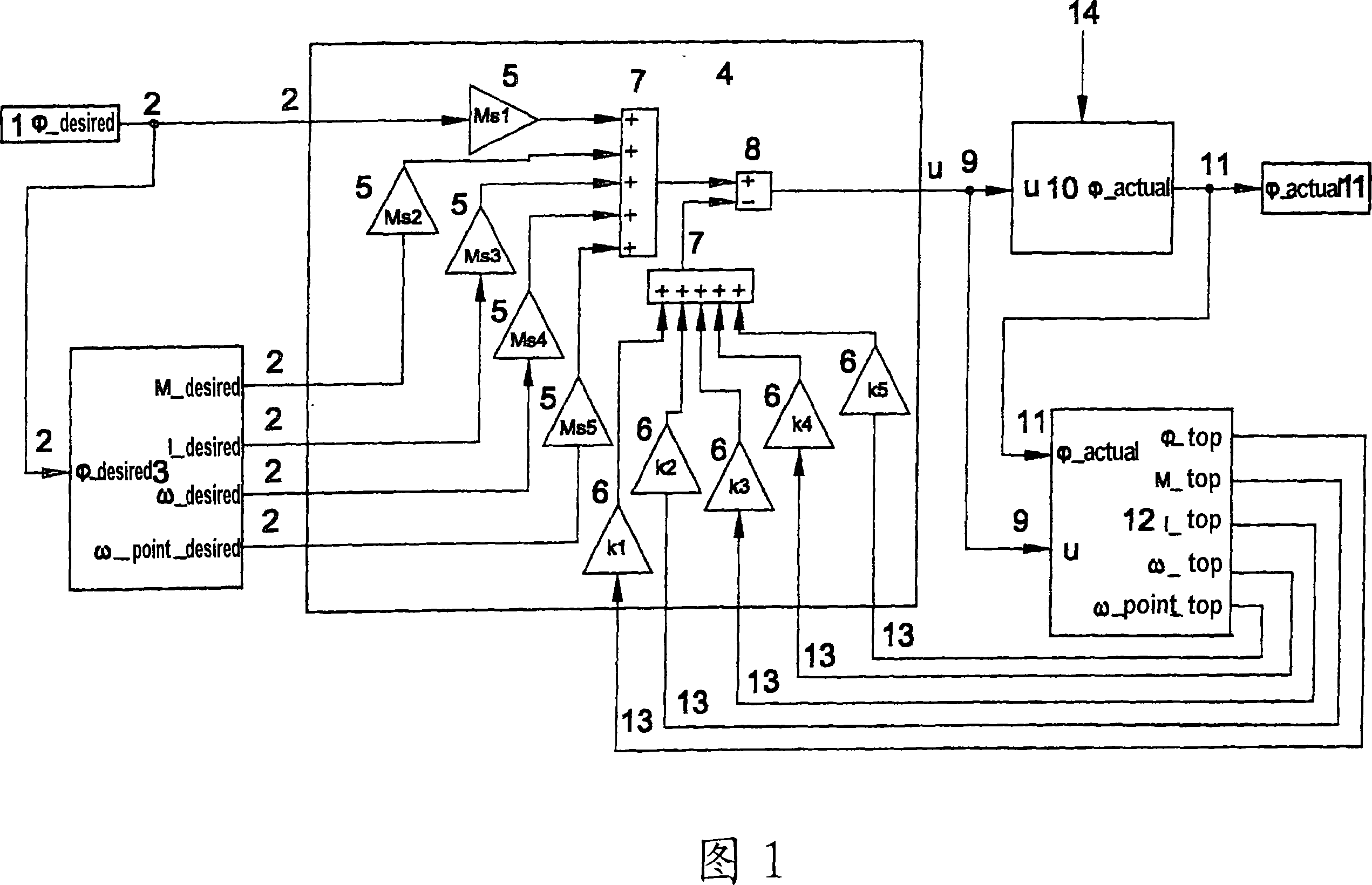
[0026] FIG. 1 shows a block diagram for a control structure of a yarn displacement drive with a state observer 12 . In this case, the predetermined angular position ([phi]_desired) enters the controller 4 directly from the desired value sensor 1 as the desired variable 2 . This angular position ([phi]_desired) is also used as an input variable in part Model 3. Using the partial model 3, the real control section 10 including the yarn guide drives and other electromechanical yarn displacement drives is described as an ideal control section. Therefore, further desired variables 2, namely the corresponding torque (M_desired), the required displacement current (I_desired), the corresponding angular velocity (ω_desired) and the corresponding angular acceleration (ω_point_desired) of the yarn guide, can be generated as parameters of the controller 4 Other input variables. Within the controller 4 , each input desired variable 2 can be individually weighted by means of a respective w...


PUM


Abstract

The invention provides a mechanism for controlling the displacement of a yarn, in particular for a workstation of a textile machine, comprising a yarn guide, a single motor drive provided therefor, for determining the actual angular position (11) of the yarn guide ( f_real) and a controller (4) for predetermining at least one correction variable (9)(u) of the output stage of said single motor drive to drive the yarn. The inventive mechanism for controlling the displacement of the yarn allows a higher frequency of displacement by preventing displacement errors, wherein the controller (4) includes precise control of at least one correction variable (9)(u) to control said guide Multivariable control system for the real angular position (11) (f_real) of the yarn carrier. A state monitor (12) is provided for accurately determining internal states such as in the actual control section (10) and communicating them to the controller.

Description

technical field [0001] The invention relates to a yarn displacement drive, in particular for a textile machine workstation, according to the preamble of claim 1 . Background technique [0002] It is known, for example, from document DE 198 58 548 A1 that, for the production of textile bobbins, the relevant textile bobbin is rotated on the one hand and the yarn running on the bobbin is traversed along the bobbin axis on the other hand. The traversing of the yarn takes place, for example, by means of finger yarn guides, also called scrapers. In order to generate a specific or predetermined winding configuration within the bobbin to be produced, the drive of the bobbin has to be separated from the drive of the yarn guide. Through this decoupling of the required drives, precise windings or graded precision windings can be produced. Thus, this technical measure means that winding patterns on the bobbins that can cause serious problems later during unwinding are avoided. Such t...

Claims


Application Information

Patent Timeline
IPC IPC(8): B65H54/28
CPCB65H54/2827B65H54/2884B65H2701/31
Inventor 弗朗茨-约瑟夫·弗拉姆
Owner SAURER GERMANY GMBH & CO KG
Why Eureka
Try Eureka