Small automatic aerosol dispenser

A sprayer and dispenser technology, applied in the direction of distribution devices, spray devices, packaging, etc., can solve the problems of lack of stability, impossibility, etc.

Inactive Publication Date: 2013-04-10
ZYXTUDIO DISENO E INNOVACION
View PDF6 Cites 0 Cited by
  • Summary
  • Abstract
  • Description
  • Claims
  • Application Information

AI Technical Summary

Problems solved by technology

[0009] Some examples of such devices include US patent 6,216,925, or the more recent document WO2007124554 or Spanish utility model U200802615; however, the size and weight of devices of this type make it impossible to combine them with Use with small aerosol cans

Method used


Image

  • Small automatic aerosol dispenser
  • Small automatic aerosol dispenser

Examples


Embodiment Construction

[0018] A description is given below of an example of an embodiment of the invention, which is not the only possible embodiment and therefore should not be interpreted in a restrictive manner.

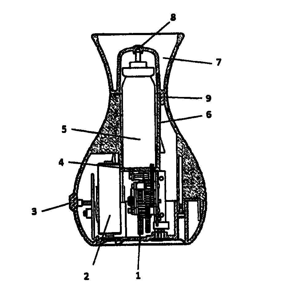
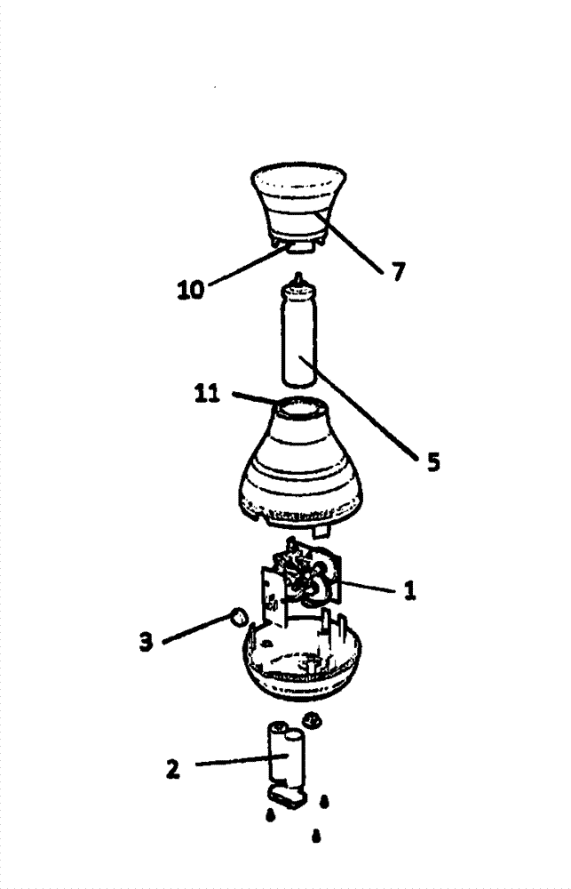
[0019] The disclosed invention relates to an automatic dispenser for a substance contained in an aerosol, such a dispenser comprising a drive element, a series of gears, a cavity for housing the aerosol canister itself, in the base of which cavity is arranged a moving element to displace the canister and press its valve against the fixed element to release the contents.

[0020] The unit includes:

[0021] The base of the device, which integrates the heavier elements, such as the battery 2 and the drive element 1 with gears, and the platform 4 on which the sprayer tank sits, also integrates the electronic components that control the device, such as the presence detection sensor 3 .

[0022] The upper area comprises a tube, inside which the aerosol can 5 can move when pushed by the pla...


PUM


Abstract

Automatic aerosol dispenser where a aerosol can (5) is in a vertical position and above a drive mechanism (1) which, by the action of a number of gears, makes the aerosol can (5) rise until the pressure exerted by its valve against the top cap (7) of the device causes the release of the aerosol contents throught a nozzle (8), after which the descent begins and the valve closes again until the cycle is initiated once more.

Description

technical field [0001] As the name suggests, the present invention relates to automatic sprayer dispensers in which, to minimize space, the sprayer is in an upright position and above a drive mechanism which, through the action of a number of gears, raises the sprayer until its valve is set against the The pressure applied by the top cap causes the release of the contents of the nebulizer until it begins to descend and the valve closes again until the cycle is started again. [0002] The invention belongs to the field of dispensers of substances, especially nebulizers. Background technique [0003] Automatic dispensers of substances contained in nebulizers are well known, including those that use a mechanism to open a valve and release the contents, and those in which the valve is constantly open and the release of the contents is regulated by an additional valve, usually actuated by a solenoid Automatic dispenser to the outside, this additional valve closes the intermediat...

Claims


Application Information

Patent Timeline
IPC IPC(8): B05B15/00B05B12/02
CPCB65D83/262B65D83/386
Inventor V·B·费奥
Owner ZYXTUDIO DISENO E INNOVACION
Why Eureka
Try Eureka