
Inner hole electroplating fixture for airplane outer barrel part

A technology of electroplating fixture and outer cylinder, which is applied in the direction of electrolysis process, electrolysis components, etc.

Active Publication Date: 2013-04-10
JIANGXI HONGDU AVIATION IND GRP
View PDF5 Cites 2 Cited by
  • Summary
  • Abstract
  • Description
  • Claims
  • Application Information

AI Technical Summary

Problems solved by technology

And there is no chromium accumulation at the part port

Method used


Image

  • Inner hole electroplating fixture for airplane outer barrel part

Examples


Embodiment Construction

[0009] In order to make the technical means, creative features, goals and effects achieved by the present invention easy to understand, the present invention will be further described below in conjunction with specific embodiments.

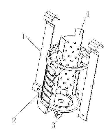
[0010] refer to figure 1 , the specific embodiment adopts the following technical solutions: the electroplating fixture for the inner hole of the outer cylinder part of the aircraft, including the cathodic protection ring 1, the upper anode positioning plate 2, the lower anode positioning plate 3 and the pictographic anode 4, and the cathodic protection ring 1 is fixed on the aircraft outer cylinder On the upper part of the part, the upper anode positioning plate 2 is fixed on the cathodic protection ring 1, the lower anode positioning plate 3 is fixed on the bottom of the outer cylinder part of the aircraft, and the pictographic anode 4 is fixed between the upper anode positioning plate 2 and the lower anode positioning plate 3.

[0011] Accordin...


PUM


Abstract

The invention discloses an inner hole electroplating fixture for an airplane outer barrel part, and relates to the electroplating field of airplane parts. The inner hole electroplating fixture for the airplane outer barrel part comprises a cathode protection ring (1), an upper anode locating plate (2), a lower anode locating plate (3) and a conformal anode (4), wherein the cathode protection ring (1) is fixed at the upper end of the airplane outer barrel part; the upper anode locating plate (2) is fixed on the cathode protection ring (1); the lower anode locating plate (3) is fixed at the bottom of the airplane outer barrel part; and the conformal anode (4) is fixed between the upper anode locating plate (2) and the lower anode locating plate (3). The inner hole electroplating fixture disclosed by the concrete embodiment solves the problems that an anode and an inner hole are not easily arranged in a concentric way, and the conformal anode easily deforms when being heated. Therefore, the problems that a plating layer is unilateral-shaped or ellipse and is not even can be solved, and the inner hole size plating requirement on the part can be met.

Description

technical field [0001] The invention relates to the field of electroplating of aircraft parts, in particular to an electroplating fixture for inner holes of outer cylinder parts of aircraft. Background technique [0002] The outer cylinder parts of the aircraft require chrome plating on the size of the inner hole. The traditional mounting method: the parts are insulated with iron sheets, and the inner holes are made of lead sheets as pictographic anodes and fixed with iron wires. This method is likely to cause pictographic anodes to not be well fixed in the center. The position of the anode and the inner hole cannot be concentric and coaxial, and the lead skin (δ=1mm) is easily deformed due to overheating during the electroplating process, making the coating unilateral, uneven, the inner hole is elliptical, and the port is easy to produce Chromium tumors and other phenomena cannot meet the requirements for inner hole size plating. Contents of the invention [0003] In...

Claims


Application Information

Patent Timeline
Patent Type & Authority Applications(China)
IPC IPC(8): C25D17/08C25D7/04
Inventor 游丽梅钱志强忻坚静李春明张金昌钟雪玲
Owner JIANGXI HONGDU AVIATION IND GRP
Learn More