Illumination device

A technology for lighting devices and fixed positions, which is applied to lighting devices, components of lighting devices, lighting and heating equipment, etc., and can solve problems such as the inability to adjust the lighting angle

Inactive Publication Date: 2013-04-10
EVERLIGHT ELECTRONICS
View PDF4 Cites 7 Cited by
  • Summary
  • Abstract
  • Description
  • Claims
  • Application Information

AI Technical Summary

Problems solved by technology

Although the reflector cup of some downlights can be rotated, it can only change the light emitting direction of the downlight, and the lig

Method used


Image

  • Illumination device
  • Illumination device
  • Illumination device

Examples


no. 1 approach

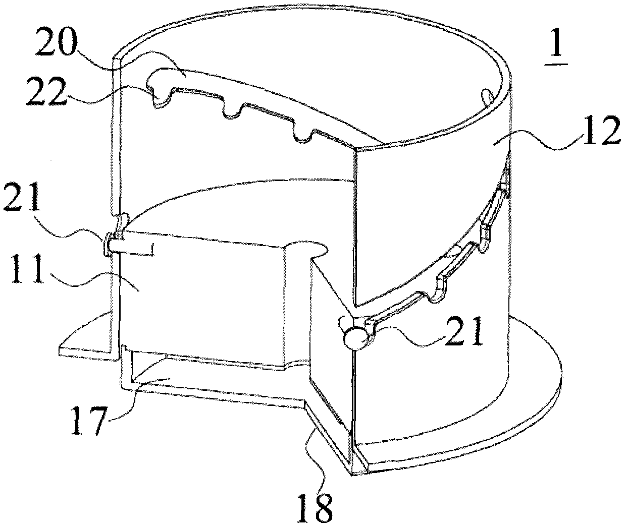
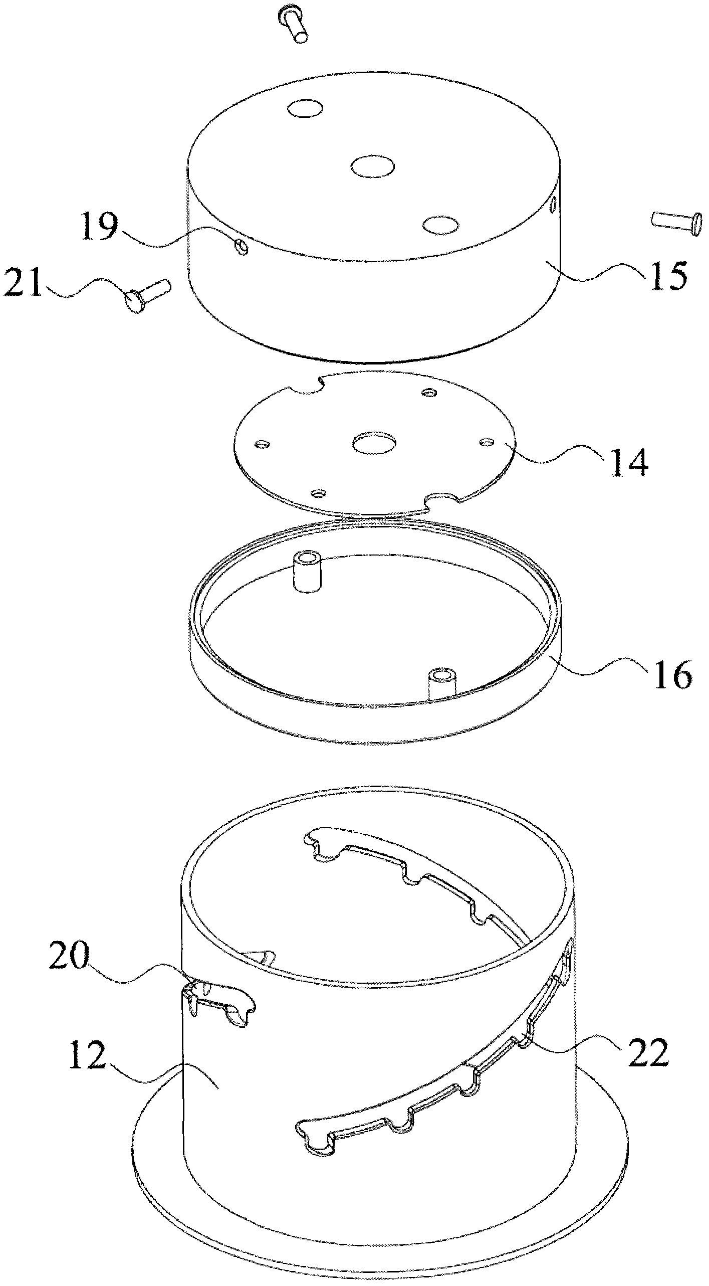
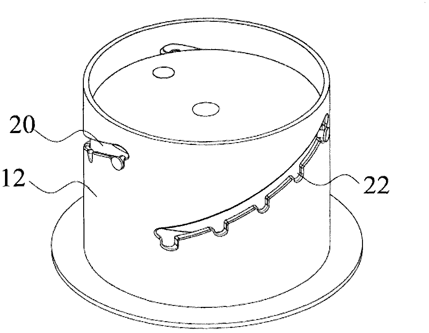
[0034] Such as figure 1 , figure 2 with image 3 As shown, a lighting device 1 includes a substantially columnar light emitting module 11 and a cover 12 surrounding the light emitting module 11 . The light-emitting module 11 of the lighting device shown in this embodiment is cylindrical, and the outer cover 12 is cylindrical, but it is only for illustration and not intended to limit the present invention. The light-emitting module 11 includes a light source (for example, an LED light panel) with the light emitting direction facing downward, a driving circuit (not shown) connected to the light source 14, a heat sink 15 positioned above the light source 14 and connected to the light source 14, and a light source arranged on the light source 14. Optics 16 on the way. A light emitting surface 17 is formed at the bottom of the light emitting module 11 , and an opening 18 is formed at the bottom of the outer cover 12 for the light emitted by the light emitting module 11 to exit....

no. 2 approach

[0042] Such as Image 6 As shown, the lighting device 3 of the second embodiment of the present invention is the same as the lighting device 1 of the first embodiment except for the limiting groove 26, so the same corresponding parts are used with figure 1 with figure 2 The same reference numerals indicate. The limiting groove 26 of the lighting device 3 extends in a stepped shape on the housing 12 and includes a plurality of alternate horizontal grooves 27 and vertical grooves 28 , the horizontal grooves 27 extend horizontally, and the vertical grooves 28 extend vertically. The horizontal grooves 27 and the vertical grooves 28 are alternately connected end to end, and are in the shape of steps. A limiting hole 29 communicating with the limiting groove 26 is provided at each corner below the steps. Each limiting hole 29 is located at the bottom of the corresponding vertical slot 28 and communicates with the corresponding vertical slot 28 .

[0043] When it is necessary to ...


PUM


Abstract

The invention discloses an illumination device, which comprises a luminous module and an outer cover surrounding the luminous module. An emergent surface is arranged at the bottom end of the luminous module. An opening is formed in the bottom end of the outer cover. The luminous module is movably connected with the outer cover, and is provided with a plurality of different fixing positions relative to the outer cover. At different fixing positions, light beams formed by the emergency of light emitted from the emergent surface of the luminous module through the opening of the outer cover are at different beam angles. The illumination device can be used as a downlight, and when the illumination device is used, a light-emitting angle can be adjusted according to the requirements of different using environments.

Description

technical field [0001] The invention relates to an illuminating device, in particular to an illuminating device capable of adjusting the light output angle. Background technique [0002] A downlight generally refers to a lighting device that is embedded in the ceiling and emits light down. This kind of hidden lamp embedded in the ceiling, all the light is projected downward, which belongs to direct light distribution. Different reflectors, lenses, shutters, bulbs can be used to achieve different light effects. [0003] Most of the downlights are embedded, that is, they are completely embedded in the ceiling, and the light source is not exposed, so that the overall unity and perfection of the architectural decoration can be maintained, and the ceiling art will not be affected by the setting of the lamps. The embedded downlight is a directional lighting fixture. Ordinary surface-mounted lights have a better spotlight effect, but they are not as strong as spotlights, which ca...

Claims


Application Information

Patent Timeline
IPC IPC(8): F21S2/00F21V19/02F21Y101/02F21K9/20F21Y115/10
Inventor 何丽丽裴建昌
Owner EVERLIGHT ELECTRONICS
Why Eureka
Try Eureka