Processing technology of pin type composite insulator

A composite insulator and processing technology, applied in insulators, electrical components, circuits, etc., can solve problems such as troublesome and high labor intensity, and achieve the effect of improving work efficiency, facilitating assembly, and reducing manual labor.

Inactive Publication Date: 2020-12-25
JIANGSU XIANGYUAN ELECTRIC EQUIP
View PDF10 Cites 2 Cited by
  • Summary
  • Abstract
  • Description
  • Claims
  • Application Information

AI Technical Summary

Problems solved by technology

[0004] At present, in the production process of pin-type composite insulators, when injecting silicone rubber on the surface of the insulating pin body to form an umbrella skirt, due to the characteristics of the structure of the injection mold itself, it is necessary to leave space on both sides of the injection cavity. The opening through which the insulating needle passes, and the insulating needle and the opening are not tightly fitted. Therefore, during injection, when the pressure is too high, part of the silicone rubber will be squeezed from the gap between the opening and the insulating needle. As a result, redundant rubber sleeves will be formed on both sides of the insulating needle body, and the upper and lower fittings need to be connected to both sides of the insulating needle body, so it is necessary to remove this part of the redundant rubber sleeves before assembling. It is very troublesome; in addition, in the subsequent assembly process, the upper fitting and the insulating needle are threaded, and due to the special shape of the upper fitting, it is elliptical, so when locking When it is impossible to use a conventional wrench for locking, it is necessary to manually move the upper fitting and the insulating needle body to carry out the needle body, which is labor-intensive.

Method used


Image

  • Processing technology of pin type composite insulator
  • Processing technology of pin type composite insulator
  • Processing technology of pin type composite insulator

Examples


Embodiment Construction

[0034] The following examples can enable those skilled in the art to understand the present invention more comprehensively, but the present invention is not limited to the scope of the described examples.

[0035] like Figure 7 The schematic diagram shown shows that the pin composite insulator includes

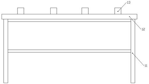
[0036] An insulating needle body 1 has a shed 2 on the outer surface of the insulating needle body 1, and upper fittings 3 and lower fittings 4 are installed on both sides of the insulating needle body 1 respectively.

[0037] The upper fitting 3 is T-shaped as a whole, and the upper end surface of the upper fitting 3 is elliptical. There is a mounting groove 5 in the middle of the upper end surface of the upper fitting 3. The upper fitting 3 and the insulating needle body 1 are threaded and fixed. The outer wall on the upper side of the needle body 1 has an external thread structure, and the bottom end of the upper fitting 3 has a threaded through hole embedded with the top...


PUM


Abstract

The invention relates to a processing technology of a pin type composite insulator. The processing technology comprises the following steps of respectively processing a required insulating pin body, an upper fitting, a lower fitting and a grading shield; feeding the processed insulating pin body into injection equipment, respectively arranging a blocking plug at two sides of the insulating pin body during injection in a sleeving manner, blocking openings at two sides of an umbrella skirt injection cavity, starting injection and performing vulcanization molding to form an umbrella skirt; feeding the insulating pin body with the umbrella skirt to a special assembly system for assembling; and feeding the assembled pin type composite insulator into a storage system for storing, thereby finishing processing. The processing technology disclosed by the invention has the advantages that during injection, the openings at two sides of the umbrella skirt injection cavity are blocked by utilizingthe blocking plugs, the condition that partial silicone rubber flows out of the openings and forms excessive rubber sleeves on the insulating pin body due to excessive pressure is avoided, and only the blocking plugs need to be removed during subsequent treatment, so that the processing technology is very convenient.

Description

technical field [0001] The invention relates to the field of processing composite insulators, in particular to a processing technology for pin-type composite insulators. Background technique [0002] The selection of an insulator that is resistant to lightning strikes, pollution flashover and long life is of great significance to the safe operation of the line and its equipment and to ensure the reliability of the power supply of the line. [0003] Composite insulators are composed of core rods made of epoxy glass fiber rods and silicon rubber as the basic insulator. The mechanical strength of epoxy glass fiber rods is quite high, which is 1.6 to 2.0 times that of ordinary steel and 3 times that of high-strength porcelain. 5 times. [0004] At present, in the production process of pin-type composite insulators, when injecting silicone rubber on the surface of the insulating pin body to form an umbrella skirt, due to the characteristics of the structure of the injection mold...

Claims


Application Information

Patent Timeline
Patent Type & Authority Applications(China)
IPC IPC(8): B29C69/00B29C45/14B29C65/64H01B19/00
CPCB29C69/00B29C45/14B29C65/64B29C65/561B29C66/74285B29C66/80H01B19/00
Inventor 张德进刘铁桥张斌张达武纪福俊章玉秀朱勇飞王丹丹秦锦华
Owner JIANGSU XIANGYUAN ELECTRIC EQUIP
Why Eureka
Try Eureka