
A maintenance-free full-proof floor drain

A maintenance-free, floor drain technology, which is applied in the field of daily kitchen and bathroom appliances, can solve the problems of unresolved hair fibers, accumulation, and unresolved sewer gas leakage, so as to prevent odor from rising, improve sealing effect, and improve airtightness Effect

Active Publication Date: 2018-08-14
哈尔滨千奇环境技术有限公司
View PDF7 Cites 2 Cited by
  • Summary
  • Abstract
  • Description
  • Claims
  • Application Information

AI Technical Summary

Problems solved by technology

[0004] Another problem with this solution is that the shape design and connection method of the water baffle and the lever do not solve the problem of easy accumulation of hair fibers, and at the same time, the traditional floor drain does not solve the problem of sewer air leakage

Method used


Image

  • A maintenance-free full-proof floor drain
  • A maintenance-free full-proof floor drain
  • A maintenance-free full-proof floor drain

Examples


Embodiment 1

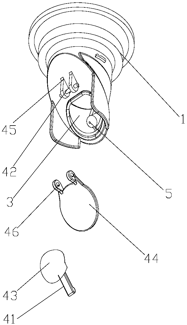
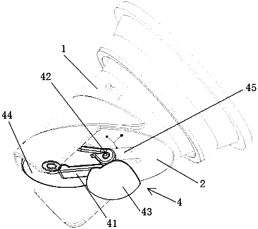
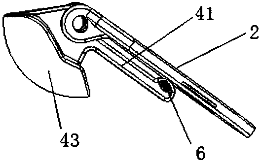
[0028] like Figure 1 to Figure 4 As shown, a maintenance-free and full-proof floor drain includes a hollow floor drain core 1, and the floor drain core 1 is provided with a sealing plate 2 for separating the upper part and the lower part of the floor drain core 1. The sealing A water outlet 3 is provided on the plate 2, and a water retaining structure 4 is provided below the sealing plate 2, and the water retaining structure 4 includes a lever 41, a rotating shaft 42 used as a fulcrum of the lever 41, and a shaft arranged at one end of the lever 41. The counterweight 43, the water retaining plate 44 arranged between the water outlet 3 and the other end of the lever 41, the water retaining plate 44 is rotatably connected to the rotating shaft 42 and is used to seal fit with the water outlet 3; The moment of weight 43 is greater than the moment of water baffle 44 . It should be noted that the moment of the water baffle 44 refers to the product of the distance from the gravity ...

Embodiment 2

[0036] like Figure 5 As shown, on the basis of Embodiment 2, a floor drain cover 9 is provided above the floor drain core 1, and the floor drain cover 9 includes a hollow cover body 91, and the cover body 91 is provided with a plurality of A filter bar 92 inclined downward from the head end to the tail end, the head end of the filter bar 92 is fixed on the cover body 91, and the tail end of the filter bar 92 is a free end. The cover body 91 is circular or square, the hollow portion of the cover body 91 is circular, the distance between two adjacent filter bars 92 is 6mm, and the inclination angle of the filter bars 92 is 20° A support body 90 is provided above the hollow part of the cover body 91, the support body 90 includes a support body 93 and a support rod 94 connected to the support body 93, and the end of the support rod 94 is connected to the cover On the body 91, the upper surface of the support body 93 is an upwardly protruding arc surface. In the direction from th...

Embodiment 3

[0039] like Image 6 As shown, it is substantially the same as Embodiment 2, except that the hollow part of the floor drain cover 9 of this embodiment is rectangular, the support body 90 is strip-shaped, and the filter strips 92 are respectively arranged on both sides of the support body 90 .


PUM


Abstract

The invention discloses a maintenance-free fully-preventive floor drain, comprising a hollow floor drain core, wherein a seal plate for spacing the upper and lower parts of the floor drain core is arranged in the floor drain core, a water outlet is arranged on the seal plate, a water retaining structure is arranged below the seal plate and comprises a lever, a rotating shaft used as a lever fulcrum, a clump weight arranged at one end of the lever and a water-retaining plate arranged between the water outlet and the other end of the lever, the water-retaining plate is in rotary connection with the rotating shaft and is used for seal fit with the water outlet, and the moment of the clump weight is greater than the moment of the water-retaining plate. The invention aims at providing the maintenance-free fully-preventive floor drain which is capable of thoroughly solving the problem of hair fiber accumulation, has good seal effect and prevents blow-by.

Description

technical field [0001] The invention relates to the field of daily-use kitchen and bathroom appliances, in particular to a maintenance-free and fully anti-floor drain. Background technique [0002] The floor drain cover is a commonly used component in the kitchen and bathroom space. There are widespread problems that fibers and hair are easy to accumulate, and small parts are easy to enter the sewer. [0003] Chinese patent ZL 201120344980.9 discloses an improved floor drain, which includes a floor drain body and a floor drain cover; a sealing plate for sealing and separating the upper and lower parts of the floor drain body is provided in the floor drain body, and the sealing plate is provided with a water outlet , a rotating shaft is installed on the bottom side of the sealing plate, a counterweight is connected to one end of the rotating shaft and a lever is connected to the other end of the rotating shaft, a water retaining plate is tightly matched with the water outlet,...

Claims


Application Information

Patent Timeline
Patent Type & Authority Patents(China)
IPC IPC(8): E03F5/04E03F5/06
CPCE03F5/0407E03F5/06
Inventor 于树贵于小航
Owner 哈尔滨千奇环境技术有限公司
Learn More