Online fault location method and equipment of radio frequency transmission line

A radio frequency transmission, fault location technology, applied in transmission monitoring, transmission system, transmission channel monitoring and other directions

Active Publication Date: 2013-04-10
成都长峰信测科技有限公司
View PDF5 Cites 18 Cited by
  • Summary
  • Abstract
  • Description
  • Claims
  • Application Information

AI Technical Summary

Problems solved by technology

[0008] The purpose of the present invention is to provide a radio frequency transmission line online fault location method and equipment that can effectively solve the problems existing in the fault monitoring technology of the existing two types of radio frequency transmission lines

Method used


Image

  • Online fault location method and equipment of radio frequency transmission line
  • Online fault location method and equipment of radio frequency transmission line
  • Online fault location method and equipment of radio frequency transmission line

Examples


Embodiment Construction

[0029] The specific embodiments of the present invention will be further described in detail below in conjunction with the accompanying drawings.

[0030] The online fault location method of the radio frequency transmission line in the present invention is only in the single-ended test of the radio frequency transmission line (hereinafter referred to as the radio frequency transmission line under test), specifically as follows:

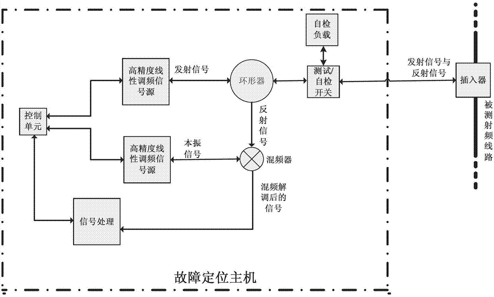
[0031] Such as figure 1 As shown, at one end of the RF transmission line under test, without affecting the normal line operation, an inserter is connected, and the out-of-band detection frequency of the communication operating frequency close to the RF transmission line under test is output in an online manner through the inserter. signal, the out-of-band detection signal is a chirp signal generated by a high-precision chirp signal source in the fault location host, and the chirp signal is divided into two lines of chirp signals by the control unit, o...


PUM


Abstract

The invention discloses an online fault location method and equipment of a radio frequency transmission line, wherein the online fault location method of the radio frequency transmission line includes that an online test is conducted on the tested radio frequency transmission line at a single end of the radio frequency transmission line, namely, on the premise of not influencing normal working of the line, an interposer is connected with one end of the tested radio frequency transmission line, a high-precision linear frequency modulation signal source which is controlled by a control unit of a fault location main machine produces linear frequency modulation frequency signals, and the frequencies of the linear frequency modulation frequency signals are close to communication working frequencies. A scanning test on the tested radio frequency transmission line is started through the interposer in a method of online. The scanning test is conducted from one end of the tested radio transmission line to the other end of the tested radio transmission line, the one end of the tested radio frequency transmission line is close to the interposer and the other end of the tested radio transmission line is further away from the interposer. Return losses and standing waving values of each position and corresponding positions in the tested radio frequency transmission line, an interface, a wire jumper, a phase adjusting head, a lightning arrester, a direct current separator or all the transmission line of an antenna are tested, and the interface, the wire jumper, the phase adjusting head, the lightning arrester, the direct current separator and the antenna are connected with the tested radio frequency transmission line. And a specific position of a fault in the tested radio frequency transmission line is displayed.

Description

technical field [0001] The present invention relates to a radio frequency transmission line monitoring technology in the field of communication and signal, more specifically, relates to a radio frequency transmission line monitoring technology applied in the fields of communication, railway communication and signal, urban rail transit communication and signal, etc., wherein the radio frequency Transmission lines include: RF cables, leaky cables (a special type of RF cable), waveguides, antennas, etc. Background technique [0002] There are two types of existing fault monitoring technologies and devices for radio frequency transmission lines: [0003] The first category is offline portable detectors. This kind of offline portable detectors cannot realize online real-time monitoring. It is necessary to manually carry the portable detectors to the site and carry out detection along the transmission line. There are difficulties in maintenance work, waste of manpower, and ineffec...

Claims


Application Information

Patent Timeline
Patent Type & Authority Applications(China)
IPC IPC(8): H04B17/00H04B17/30
Inventor 贺疆巍
Owner 成都长峰信测科技有限公司
Why Eureka
Try Eureka