
Ink supply device and ink supply method for inkjet recording apparatus

An inkjet recording and ink supply technology, applied in printing and other directions, can solve the problems of air bubbles flowing to the side of the inkjet head and unable to degas the air bubbles

Active Publication Date: 2013-04-24
KONICA MINOLTA IJ TECHNOLOGIES INC
View PDF7 Cites 8 Cited by
  • Summary
  • Abstract
  • Description
  • Claims
  • Application Information

AI Technical Summary

Problems solved by technology

[0006] However, although the degassing module provided in the conventional inkjet printer described in the above-mentioned Patent Document 1 can remove the dissolved gas contained in the ink, it cannot degas the visible air bubbles, so that the air bubbles flow to the inkjet printer. head side problem

Method used


Image

  • Ink supply device and ink supply method for inkjet recording apparatus
  • Ink supply device and ink supply method for inkjet recording apparatus
  • Ink supply device and ink supply method for inkjet recording apparatus

Examples


Embodiment Construction

[0044] [Overview of Inkjet Recording Device]

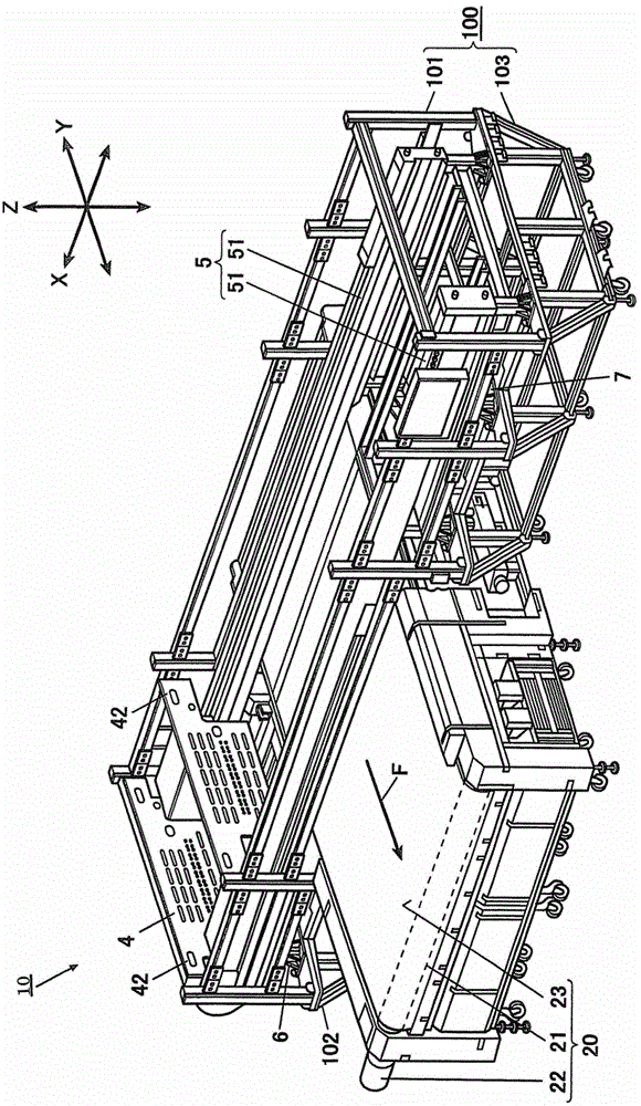
[0045] Below, refer to Figure 1 to Figure 11 An embodiment, that is, an inkjet recording device 10 equipped with an ink supply device will be described. figure 1 It is a perspective view showing the whole of the inkjet recording device 10 .

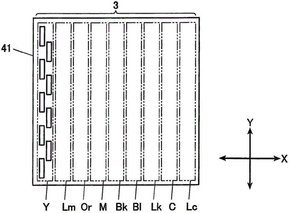
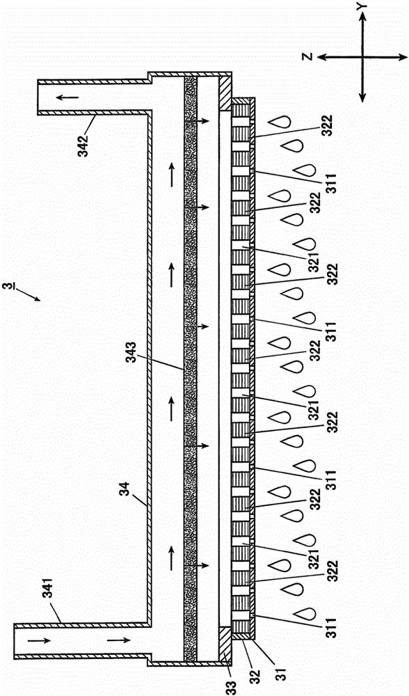
[0046] The inkjet recording device 10 mainly has: a conveying device 20 that conveys a recording medium in the horizontal direction, and a plurality of inkjet heads 3 that eject ink from the conveyed recording medium from above (refer to figure 2 ), the main scanning device 5 that transports the carriage 4 in the horizontal direction perpendicular to the conveying direction of the recording medium, the maintenance unit 7 that maintains the inkjet heads 3 mounted on the carriage 4, and the carriage 4 4 The nozzle moisturizing unit 6 for moisturizing the nozzles 311 of each inkjet head 3 mounted on the carriage 4, and the ink supply device 8 for supplying ink to each inkjet head 3 mounted ...


PUM


Abstract

Disclosed is an ink supply device (8) of an inkjet recording apparatus (10) including a first tank (81) which pools ink which is to be supplied to heads (3), a second tank (82) which is provided in a middle of a path to the heads (3) from the first tank (81), a first ink feed unit (814) which feeds the ink to the second tank (82) from the first tank (81), a second ink feed unit (829) which feeds the ink to the heads side from the second tank (82) and a first ink flow path (811) which connects the first tank (81) and the second tank (82). In the ink supply device (8), an end section of the first ink flow path (811) in the second tank side is connected to the second tank (82) so that the ink flows along an inner wall of the second tank (82).

Description

technical field [0001] The present invention relates to an ink supply device and an ink supply method for supplying ink to an inkjet head included in an inkjet printer. Background technique [0002] An inkjet printer is a recording device capable of forming images on various recording media such as plain paper and plastic sheets. An inkjet printer has an inkjet head that ejects ink from nozzle holes, and can form an image on a recording medium by ejecting fine droplets of ink from the nozzle holes of the inkjet head to the recording medium. [0003] The inkjet head is connected to an ink cartridge storing ink, and ink is supplied to the inkjet head from the ink cartridge. [0004] At this time, if dissolved gas or air bubbles are mixed in the ink, the internal volume will change, which will cause the ink ejection effect of the inkjet head that ejects the liquid droplets to deteriorate. A degassing module for vacuum degassing is provided between the ink heads to remove the ...

Claims


Application Information

Patent Timeline
IPC IPC(8): B41J2/175
CPCB41J2/18B41J2/175B41J2/19
Inventor 三觜拓
Owner KONICA MINOLTA IJ TECHNOLOGIES INC
Learn More