
Press key structure and balance rod thereof

A technology of balance bar and button, applied in the field of balance bar, can solve the problem of inability to penetrate the setting, so the middle part of the balance bar can only be set on the side of the keycap, which is difficult to restrain the action of the keycap, and the dimensional tolerance is difficult to accurately control, etc. problems, to achieve the effect of improving assembly accuracy and actuation accuracy, and improving actuation stability

Active Publication Date: 2013-04-24
DARFON ELECTRONICS (SUZHOU) CO LTD +1
View PDF4 Cites 11 Cited by
  • Summary
  • Abstract
  • Description
  • Claims
  • Application Information

AI Technical Summary

Problems solved by technology

Due to this structural feature, the middle part of the keycap is provided with a lifting mechanism and other components, such as elastic round protrusions (for providing resilience and triggering the switch), and the middle part of the balance bar cannot be set through, so the middle part of the balance bar can only It is installed on the side of the keycap, so that the structural restraint of the single balance bar on the keycap is only one side, and it is difficult to effectively restrain the movement of the entire keycap
In addition, the conventional balance bar is made of flexible materials, and after multiple bendings, it is difficult to accurately control the dimensional tolerances

Method used


Image

  • Press key structure and balance rod thereof
  • Press key structure and balance rod thereof
  • Press key structure and balance rod thereof

Examples


Embodiment Construction

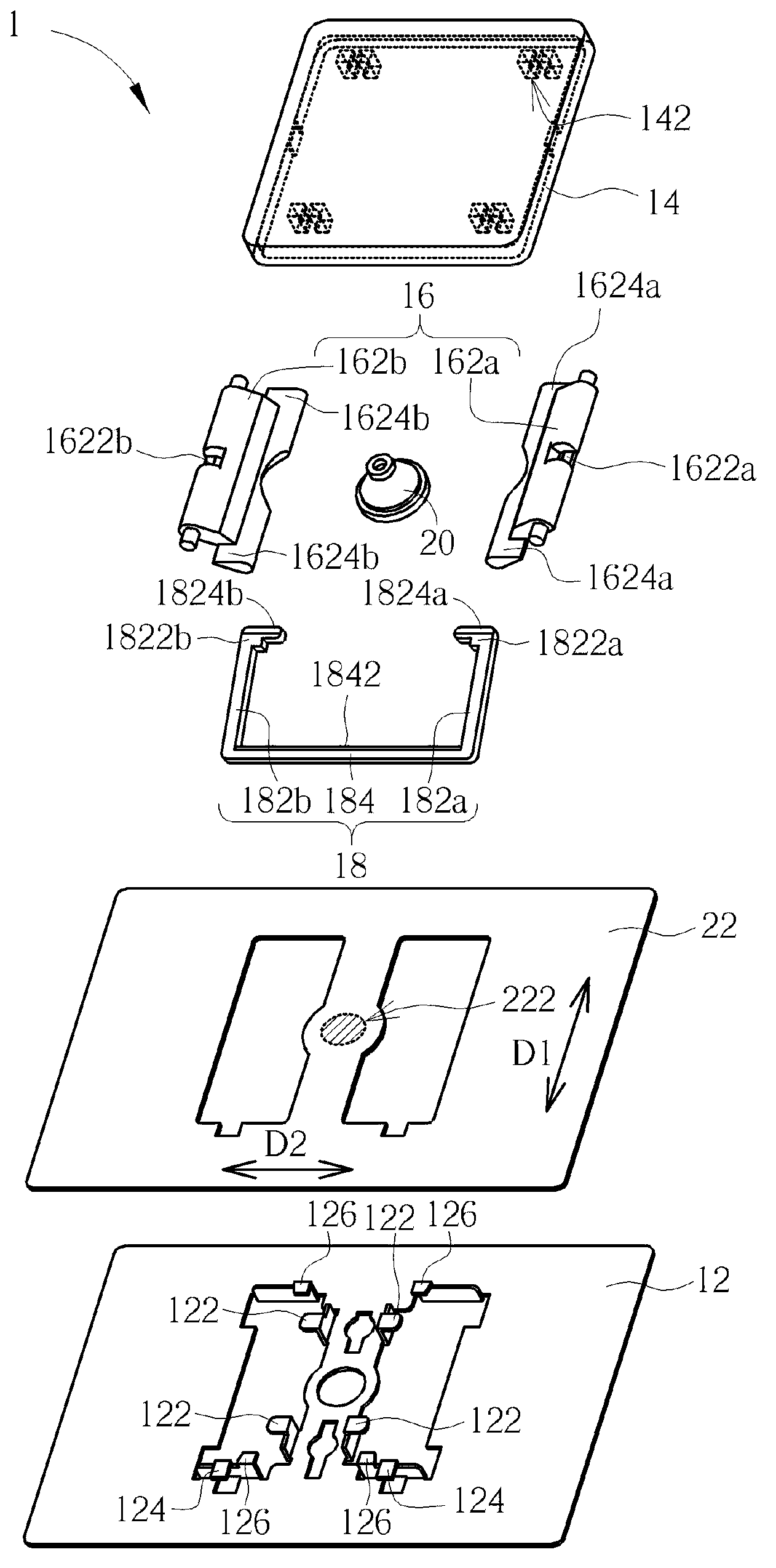
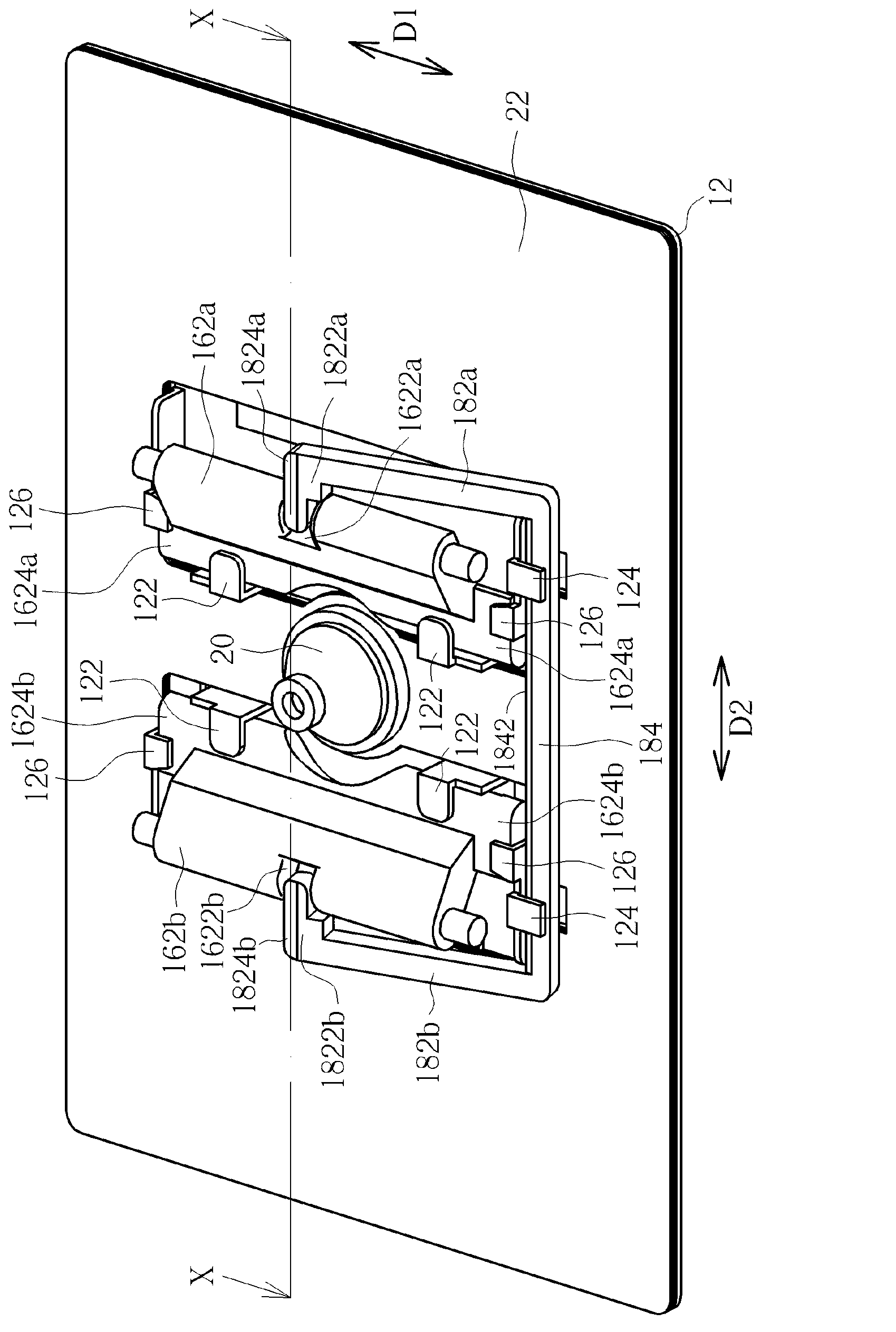
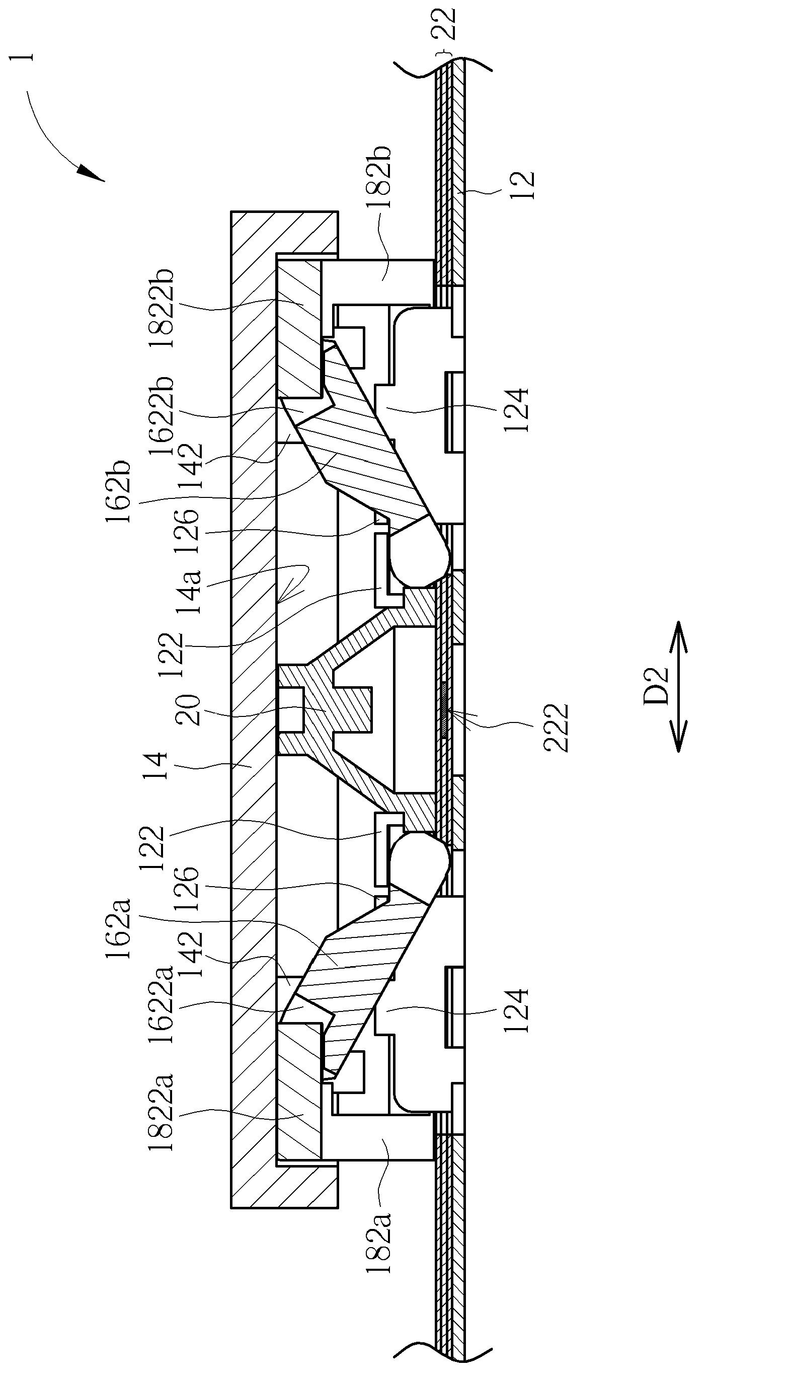
[0040] see Figure 1 to Figure 3 , figure 1 It is an exploded view of the key structure 1 according to an embodiment of the present invention, figure 2 It is a combination diagram of button structure 1, image 3 For key structure 1 edge figure 2 Sectional view of midline X-X. The button structure 1 includes a bottom plate 12, a keycap 14, a lifting mechanism 16, a balance bar 18, an elastic circular protrusion 20 and a thin film circuit board 22; figure 2 Among them, in order to clearly show the combined state of the key structure 1, the keycap 14 is not shown. The keycap 14 is disposed on the bottom plate 12 . The lifting mechanism 16 is provided between the bottom plate 12 and the keycap 14 and connected to the connecting structure 122 of the bottom plate 12 and the connecting structure 142 on the lower surface 14a of the keycap 14 (shown in hidden lines in figure 1 Middle), so that the keycap 14 can move up and down relative to the bottom plate 12 through the lifti...


PUM


Abstract

The invention relates to a press key structure and a balance rod thereof. The press key structure comprises a bottom plate, a keycap, a lifting mechanism and the balance rod. The lifting mechanism is connected between the keycap and the bottom plate so that the keycap can move up and down relative to the bottom plate. The balance rod is generally a U-shaped outline, and the middle portion of the balance rod is arranged on the bottom plate in a rotating mode. The tail ends of both sides of the balance rod are L-shaped wheel portions and inserted in groove structures in a rotary mode, wherein the groove structures are oppositely arranged in the keycap and the lifting mechanism or simultaneously arranged in the keycap and the lifting mechanism. Compared an existing balance rod which utilizes an n-shaped connecting keycap and the bottom plate, the press key structure provides various connections of the balance rod, and is beneficial to structural miniaturization. In addition, a support of the lifting mechanism comprises a projection portion which can be blocked by a limit structure which is arranged on the bottom plate to limit a rotating angle of the support.

Description

technical field [0001] The invention relates to a key structure, in particular to a key structure with a balance bar and a balance bar used in the key structure. Background technique [0002] The main structure of the current mechanical key structure is to connect the lifting mechanism between the key cap and the bottom plate, so that the key cap can move up and down relative to the bottom plate. The actuation stability of the keycap, including the actuation stroke and smoothness, usually depends on the lifting mechanism. When the movement stability of the lifting mechanism itself is not good, it is also difficult for the keycap to move smoothly. In addition, when the length of the keycap is long, such as a blank key, a single independent lifting mechanism cannot effectively provide the balanced elastic force of the keycap, so that the keycap is often skewed when pressed, so in practical applications, the length is longer Most of the keycaps are equipped with multiple lift...

Claims


Application Information

Patent Timeline
Patent Type & Authority Applications(China)
IPC IPC(8): H01H13/14
Inventor 许建士
Owner DARFON ELECTRONICS (SUZHOU) CO LTD
Learn More