
Miniature circuit breaker

A technology of miniature circuit breaker and disconnecting position, which is applied in the direction of protection switch operation/release mechanism, etc., which can solve the problem of inability to judge the artificial disconnection state of miniature circuit breaker.

Inactive Publication Date: 2015-01-28
LS INDAL SYST WUXI
View PDF10 Cites 0 Cited by
  • Summary
  • Abstract
  • Description
  • Claims
  • Application Information

AI Technical Summary

Problems solved by technology

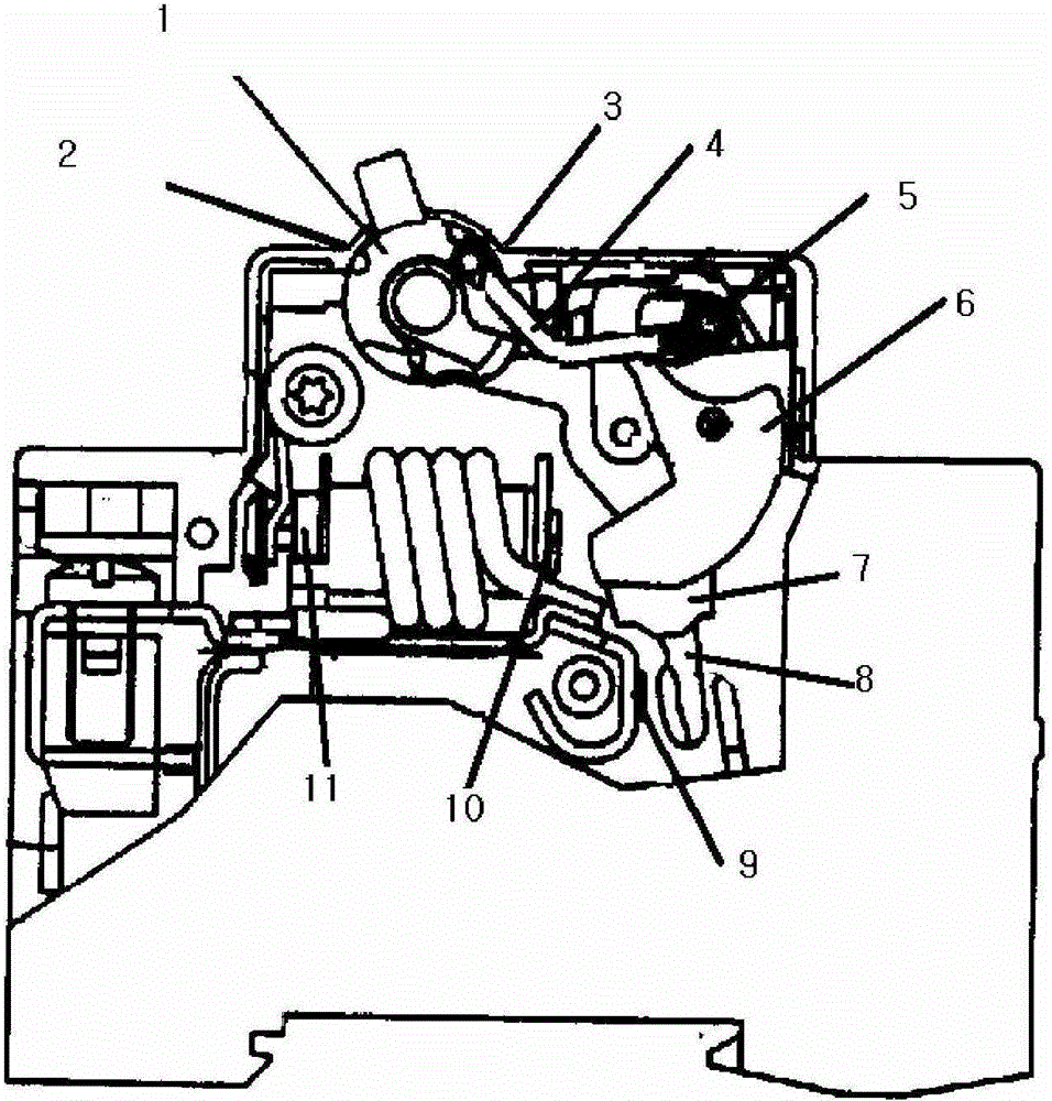
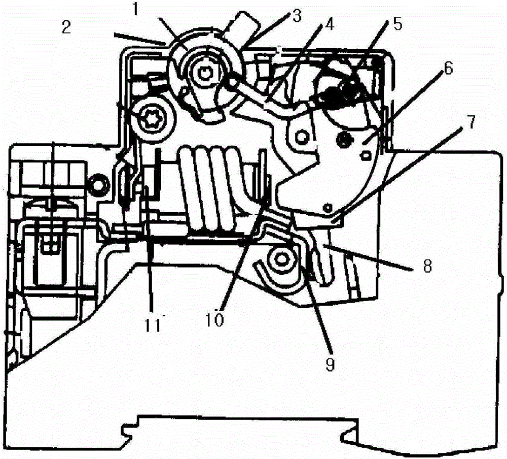
[0005] However, for the above-mentioned miniature circuit breakers in the past, since the handle 1 is located at the disconnected position 2 when the miniature circuit breaker is in the artificially disconnected state and when the circuit is disconnected due to a fault, it cannot be judged when the handle 1 is at the disconnected position 2 Whether the miniature circuit breaker is artificially disconnected or disconnected due to a fault

Method used


Image

  • Miniature circuit breaker
  • Miniature circuit breaker
  • Miniature circuit breaker

Examples


Embodiment Construction

[0024] Hereinafter, embodiments of the present invention will be described in detail with reference to the drawings.

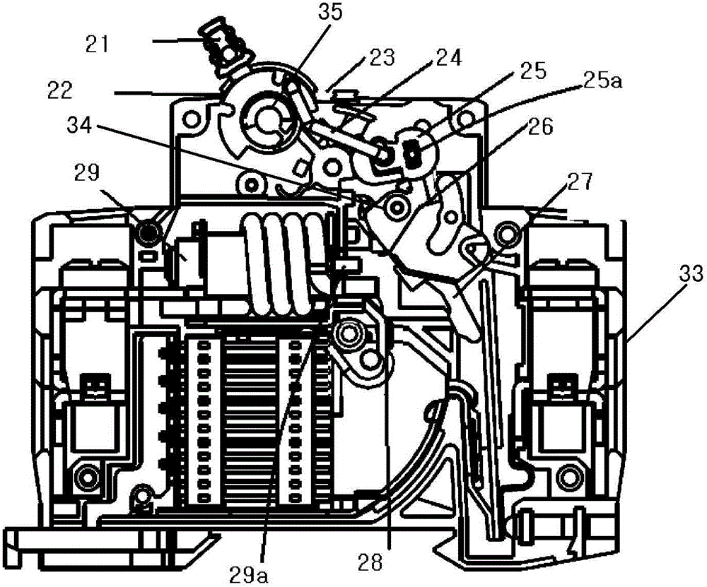
[0025] in, image 3 It is a cross-sectional view of the handle 21 of the miniature circuit breaker of the present invention when it is located at the off position 22 . Figure 4 It is a cross-sectional view of the handle 21 of the miniature circuit breaker of the present invention when it is in the ON position 23 . Figure 5 It is a sectional view of the handle 21 of the miniature circuit breaker of the present invention when it is at the post-trip position 30 . Figure 6 It is a partial cross-sectional view of the handle 21 of the miniature circuit breaker of the present invention when it is at the post-trip position 30 . Figure 7 It is a perspective view of the cover of the miniature circuit breaker of this invention. Figure 8 It is a top view of the jumper 25 of the miniature circuit breaker of the present invention. Figure 9 It is a perspective view...


PUM


Abstract

The invention relates to a miniature circuit breaker. When the miniature circuit breaker is broken by a failure, a handle can be at a middle position between an off-position and an on-position, so that a user can instantly judge that the miniature circuit breaker is broken by the failure. The miniature circuit breaker is provided with a shell. The handle, a transmission connecting rod, a jump button, a lock catch and a movable contact are arranged in the shell. A bump structure is formed on a part of the shell close to the on-position. A guide hole connected with the transmission connecting rod is formed in the jump button. In a state that the bump structure is pressed against the transmission connecting rod, a second hook part of the transmission connecting rod can move in the guide hole by means of external force.

Description

technical field [0001] The invention relates to a small circuit breaker used in overcurrent protection and short circuit protection of construction machinery and engineering machinery. Background technique [0002] Such as figure 1 As shown, the conventional miniature circuit breaker has a handle 1 , a transmission link 4 , a jump button 5 , a lock 6 , and a lever 7 . The lever 7 and the movable contact (Movable Contact) 8 are integrated to rotate. When the handle 1 is rotated, the handle 1 drives the jumper 5 through the transmission link 4, so that the lock 6 engaged with the jumper 5 and the lever 7 connected with the lock 6 are rotated, so that the moving contact 8 moves Contact with the static contact (Static Contact) 9, so that the current flows, and it becomes the ON state of the miniature circuit breaker. When the handle 1 is reversed, the jumper 5 is driven by the transmission link 4, so that the lock 6 and the lever 7 are rotated in the opposite direction, so th...

Claims


Application Information

Patent Timeline
Patent Type & Authority Patents(China)
IPC IPC(8): H01H71/62
Inventor 赵质胜金文吉
Owner LS INDAL SYST WUXI
Learn More