
High-pressure driven underwater jumping device

A high-voltage drive and packaging technology, applied in the field of jumping robots, to achieve the effect of simple and compact structure, convenient loading and unloading, and strong load capacity

Active Publication Date: 2019-05-21
HARBIN INST OF TECH SHENZHEN GRADUATE SCHOOL
View PDF5 Cites 0 Cited by
  • Summary
  • Abstract
  • Description
  • Claims
  • Application Information

AI Technical Summary

Problems solved by technology

The current various jumping robots can only jump on land, and the amphibious bionic jumping robot with load capacity is still a research gap in the current international bionic field

Method used


Image

  • High-pressure driven underwater jumping device
  • High-pressure driven underwater jumping device
  • High-pressure driven underwater jumping device

Examples


Embodiment Construction

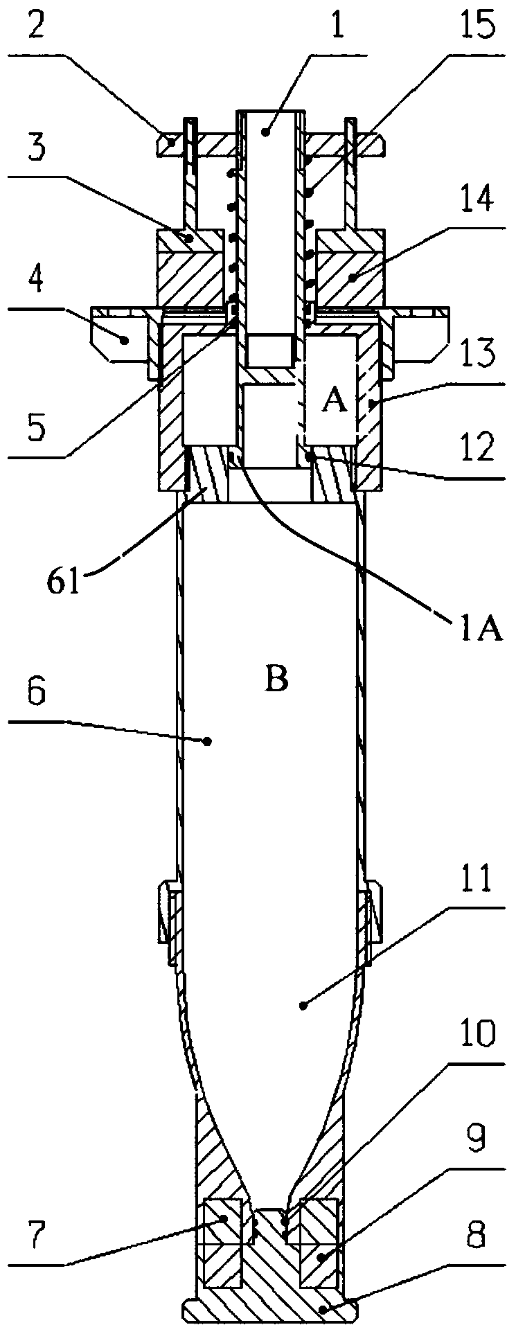
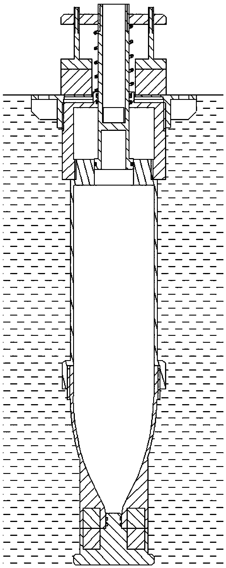
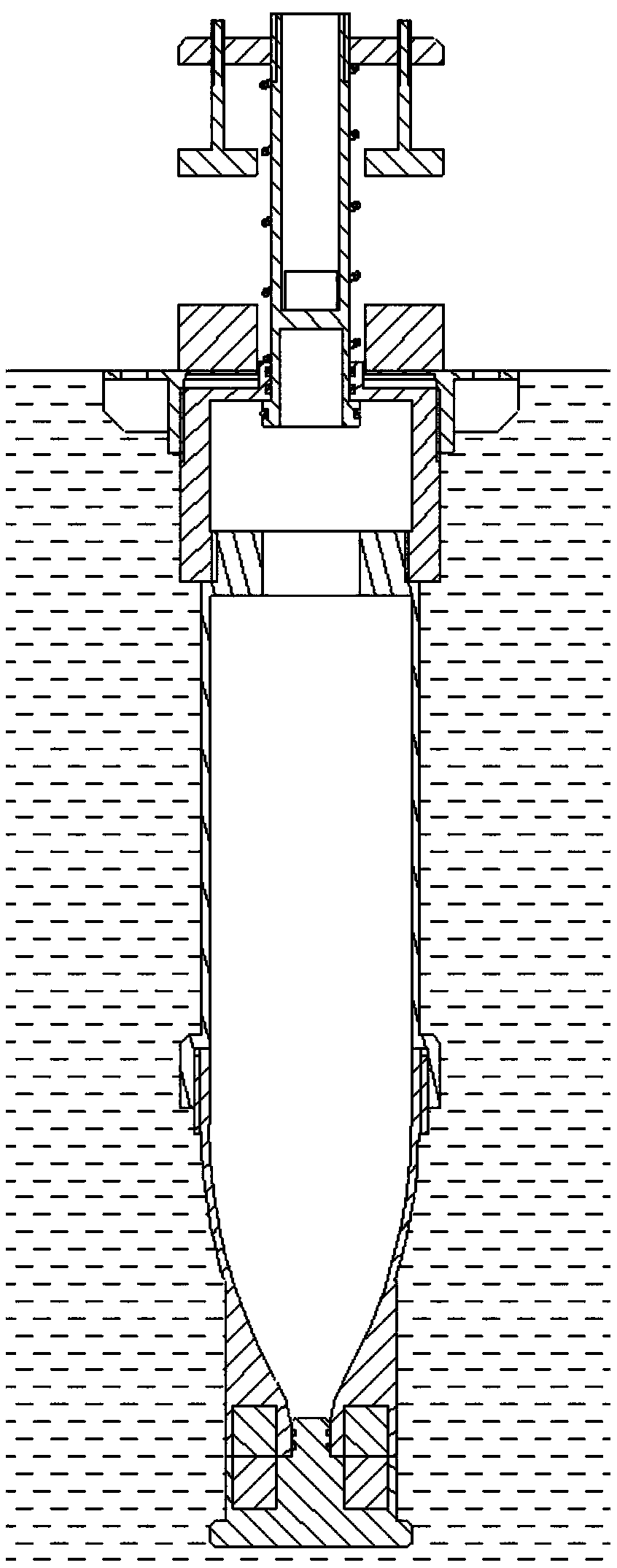
[0028] figure 1 The overall structure of a preferred embodiment of the high-voltage-driven underwater jumping device of the present invention is shown. Such as figure 1 As shown, in the high-pressure driving underwater jumping device of the present embodiment, the tank body is composed of an upper tank body 13, a middle tank body 6 and a lower tank body 11, and between the upper tank body 13 and the middle tank body 6 and the middle tank body 6 and the lower tank body 11 are threaded or welded, and the top of the middle tank body 6 has an annular partition wall 61. The annular partition wall 61 separates the inside of the tank body into an upper chamber containing the first propellant (such as liquid nitrogen). Space A and a lower accommodating space B containing a second propellant (such as water), the volume of the lower accommodating space B is larger than that of the upper accommodating space A (for example, about four times its volume). The top of the tank body is provi...


PUM


Abstract

The invention relates to a high-pressure driving underwater jumping device, comprising a tank body, a piston and a bottle stopper. An upper receiving chamber containing a first propellant and a lowerreceiving chamber containing a second propellant are formed in the tank body, an annular partition wall exists between the two receiving chambers, a through hole is formed in the top of the tank body,and a nozzle communicating with the lower receiving chamber is formed in the bottom of the tank body. The upper end of the piston protrudes out of the tank body via the through hole, the lower end ofthe piston is provided with a radial boss which is in sealing contact with the annular partition wall, an iron block bracket and an iron block mounted on the iron block bracket are fixed on the upperend of the piston, an electromagnet is arranged on the top of the tank body, and an elastic compression part is arranged between the iron block bracket and the top of the tank body. The bottle stopper is used for sealing the nozzle, and the bottom of the tank body are provided with a lower magnet and an upper magnet which are mutually adsorbed. The underwater jumping device has the advantages ofcompact structure, convenience in loading and unloading, high energy utilization rate and high load bearing capability, so that a robot has good obstacle-blocking ability and athletic ability in a water environment.

Description

technical field [0001] The invention relates to the field of jumping robots, in particular to an underwater jumping device. Background technique [0002] Amphibious robots can perform tasks in complex field environments such as oceans, tidal flats, and wetlands, and have extensive application value in battlefield reconnaissance, water quality monitoring, and life rescue. According to the division of its walking mechanism, the main amphibious robots can be divided into the following categories: spherical amphibious robots, legged amphibious robots, wheel-paddle integrated amphibious robots and snake-shaped amphibious robots. Compared with other forms of amphibious robots, legged amphibious robots have a strong ability to overcome obstacles and are highly adaptable to the environment, but the disadvantages of legged amphibious robots are that their control systems are very complex and the stability of walking deviates . Wheeled amphibious robots have relatively high walking ...

Claims


Application Information

Patent Timeline
Patent Type & Authority Patents(China)
IPC IPC(8): B63H11/16
CPCB63H11/16
Inventor 李兵莫继学苗志怀张云路郭渺辰
Owner HARBIN INST OF TECH SHENZHEN GRADUATE SCHOOL
Learn More