Dehydration of body hem flanges

a hem flange and body technology, applied in the direction of lighting and heating apparatus, drying solid materials without heat, and combination processes, etc., can solve the problems of liquid contaminants on the panel surface, partially exposed, and often incomplete drying process, so as to reduce pressure

Active Publication Date: 2007-02-27
HONDA MOTOR CO LTD
View PDF12 Cites 14 Cited by
  • Summary
  • Abstract
  • Description
  • Claims
  • Application Information

AI Technical Summary

Benefits of technology

[0010]In accordance with the present invention, the rapid evaporation of liquid contaminants from partially exposed voids is accomplished by reducing the air pressure in a zone immediately surrounding the surface of the liquid contaminant so that the boiling point is increased as a function of the reduced pressure. Accordingly, the air temperature in the zone may be at or slightly greater or less than the boiling point in the surrounding atmosphere without boiling occurring.
[0012]The high velocity airflow is produced by forcing air through one or more nozzles aimed at the location on the structure that contains the void or voids where liquid contaminants accumulate. The resulting reduction in pressure at the surface of the liquid, combined with the high ambient temperature, promotes rapid vaporization of the liquid without any boiling.

Problems solved by technology

This treatment may leave liquid contaminants on the panel surfaces, as well as in partially exposed voids such as those contained in hem flanges.
However, where the liquid has accumulated in voids, such as in a hem flange, the drying process is often not complete.
Thus, when the frame assembly is passed through a heat-treating station with temperatures in excess of 100° C., the liquid may boil off and leave defects on one or more surfaces that must be removed by a manual procedure, such as sanding.
This results in defects on frame assembly surfaces as described above.
Efforts have been made to remove these contaminants before they boil off in the heat-treating process, but the methods tried have significant disadvantages.
The first two techniques are cost-prohibitive and the last two have not been successful.

Method used


Image

  • Dehydration of body hem flanges
  • Dehydration of body hem flanges
  • Dehydration of body hem flanges

Examples


Embodiment Construction

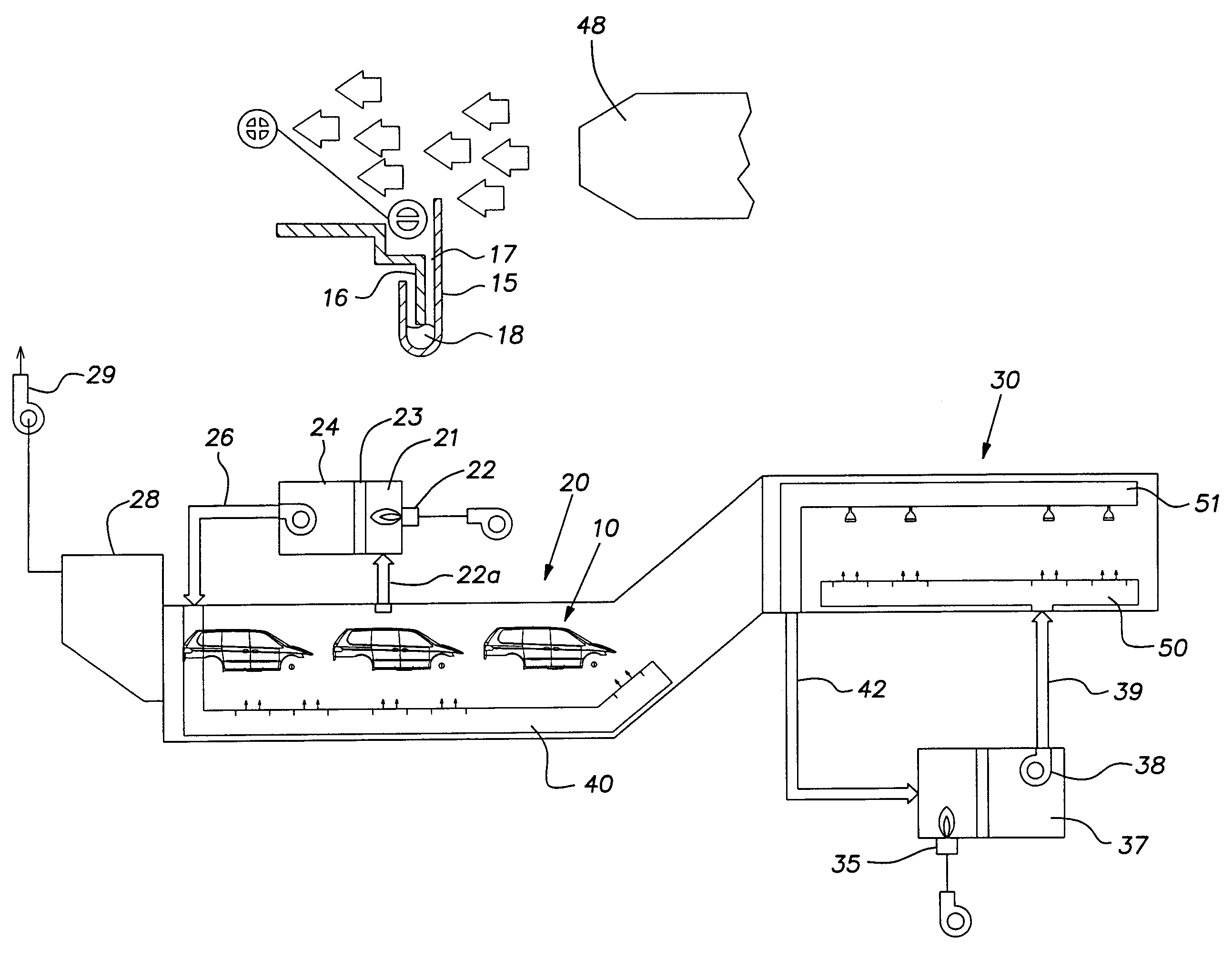
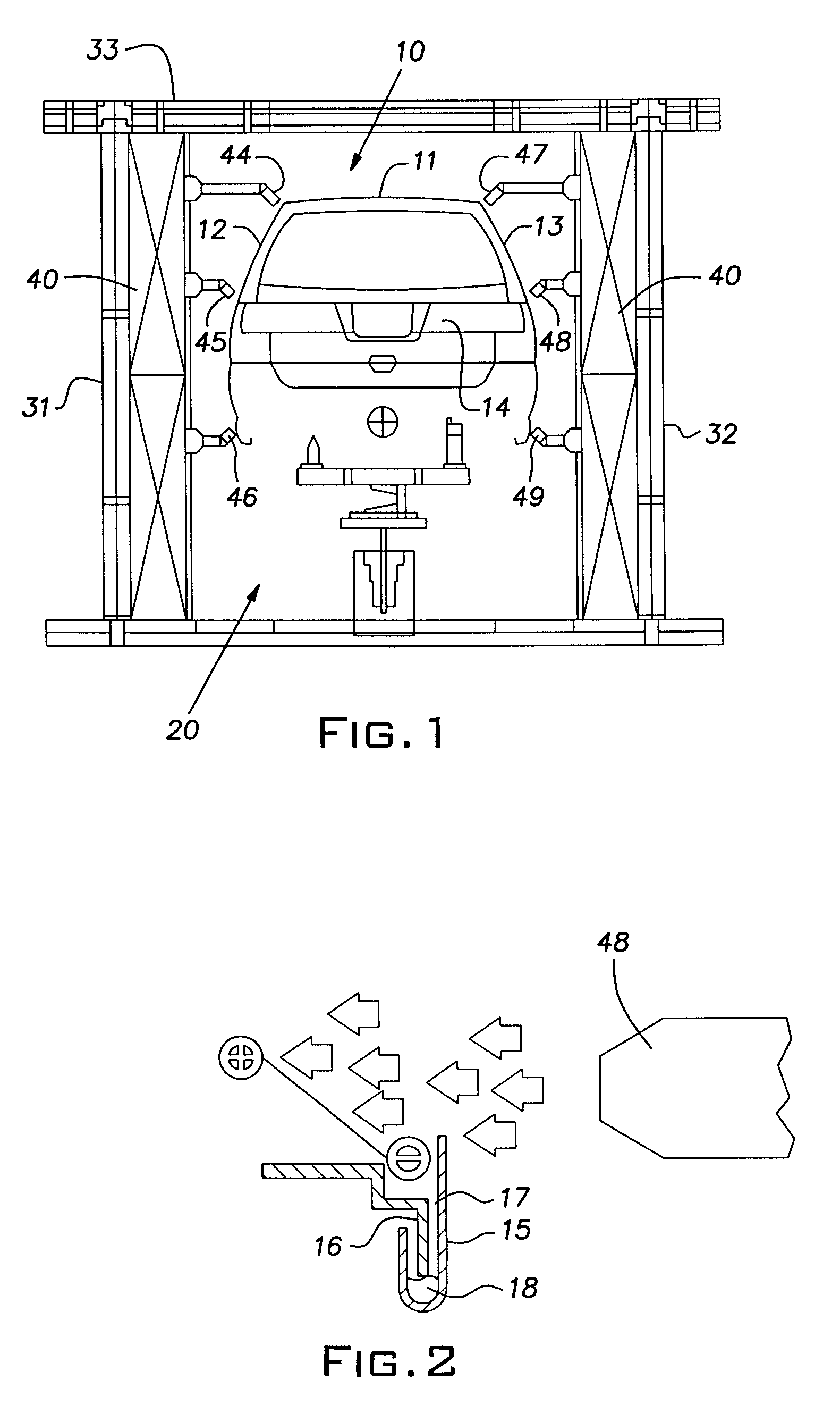
[0021]Referring more particularly to the drawings and initially to FIG. 1, there is shown a vehicle body assembly 10 fabricated from sheet metal and being conveyed through a pre-heating tunnel 20, adapted to perform the method of the invention in order to cause evaporation of liquid contaminants. The method of the invention is used simultaneously with the pre-heating of the body assembly 10, as is necessary prior to heat treating of the body assembly, as is well known in the art.

[0022]In this regard, FIG. 5 schematically shows both the pre-heat tunnel 20 and a downstream heat-treating tunnel 30. After being dipped in a tank containing, for example, a cleaning solution, the body assembly 10 (which is sometimes referred to as a ‘white body’ by those skilled in the art) is carried into the pre-heat tunnel 20. In the pre-heat tunnel 20 the body assembly 10 is gradually heated to an elevated temperature before being introduced into the heat-treating tunnel 20, in which the body assembly ...


PUM


Abstract

As a metal assembly, which defines partially open voids in which liquid accumulates is conveyed through a heat-treating station, the hot air is blown across the open end of the void to produce a zone of low pressure at the surface of the liquid. The reduction in pressure and relatively high temperature promote rapid vaporization of the liquid while discouraging boiling of the liquid.

Description

FIELD OF THE INVENTION[0001]The present invention generally relates to the heat treating and coating of fabricated sheet metal components as they move along an assembly line and, more particularly, to a method for removing liquid contaminants from partially closed voids in fabricated sheet metal assemblies where the liquid results from the assemblies being dipped in or sprayed with various cleaning and treating liquids prior to heat treating and coating processes.BACKGROUND OF THE INVENTION[0002]In the manufacture of various sheet metal components, such as in the production of vehicles, a fabricated assembly is often subjected to heat treatment at temperatures in excess of 100° C. subsequent to coating such as by dipping or spraying. In certain portions of these assemblies, such as automobile body assemblies, door frames, and the like, the assembly is formed to provide a hem flange along one or more edges in order to strengthen the frame structure. A hem flange is formed by bending ...

Claims


Application Information

Patent Timeline
Patent Type & Authority Patents(United States)
IPC IPC(8): F26B7/00
CPCF26B5/14F26B2210/12
Inventor COSS, CHRIS
Owner HONDA MOTOR CO LTD
Why Eureka
Try Eureka