[0044] The following will clearly and completely describe the technical solutions in the embodiments of the present invention with reference to the accompanying drawings in the embodiments of the present invention. Obviously, the described embodiments are only some, not all, embodiments of the present invention. Based on the embodiments of the present invention, all other embodiments obtained by persons of ordinary skill in the art without creative efforts fall within the protection scope of the present invention.
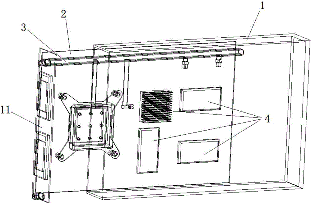
[0045] like figure 1 As shown, the present invention provides an electronic device that uses liquid cooling to dissipate heat, including a housing 1, a circuit board 2, and a liquid cooling module, and the circuit board 2 and the liquid cooling module are placed in the housing 1 , the housing 1 is composed of a plurality of wall panels to form a closed space, at least one detachable wall panel 11 is provided in the plurality of wall panels, and one or more heating devices 4 are arranged on the circuit board 2,
[0046] The liquid cooling module includes a liquid inlet pipe 3 and a nozzle communicating with the liquid inlet pipe 3, the liquid inlet pipe 3 guides the cooling liquid from the outside of the housing 1 into the housing 1, and the nozzle sprays the cooling liquid In the space formed by the housing 1 or directly sprayed on the heat-generating device 4, the temperature of the heat-generating device 4 is cooled, and the cooling liquid vapor after heat exchange is mixed with the cooling liquid sprayed from the nozzle to condense the cooling liquid vapor .
[0047] Preferably, the nozzle sprays the cooling liquid on the heat-generating device 4 in the form of spray, so as to directly cool down the heat-generating device 4 .
[0048] Preferably, the casing 1 is also provided with a power supply interface for supplying power to the heating device 4 and an IO interface for exchanging data, and these interfaces can lead power or electrical signals into, Export the shell.
[0049] Preferably, the casing 1 is also provided with a liquid inlet fixedly connected to the liquid inlet pipe 3 and a liquid outlet for discharging the cooling liquid in the casing 1, and the liquid outlet is arranged on the The lower end of the housing 1.
[0050] When an electronic device with a cooling and heat dissipation device is working, the cooling liquid that is pressed into the liquid inlet pipe is sprayed out from the nozzle. Due to the wide range of spray droplets, the spray droplets sprayed from one nozzle can easily spread to all places in the confined space. At the same time, due to the small size of the droplets, it can also reach the position that is difficult to reach with the airflow. After the droplets collide with the components, walls or other obstacles on the board, they will stick to them. When they gather to a certain amount, they will either form large droplets or form a liquid film, and fall downward under the impact of droplets and gravity. flow. The heat emitted by the heating element 4 is transferred to the liquid droplet or liquid film, and is taken away with the flow of the liquid droplet film. If the surface temperature of the heating element 4 is high, it can also promote the evaporation of the droplet liquid film, thereby enhancing the heat exchange effect. After the cooling liquid whose temperature has been raised after heat exchange is collected at the bottom of the shell, it flows out of the shell through the liquid outlet.
[0051] Specifically, there is at least one circuit board 2 , and the circuit board and the electrical components on it can realize the required functions of the electronic device.
[0052] Preferably, the liquid inlet pipe 3 includes a main pipe and a branch pipe communicating with the main pipe, and the nozzle is installed on the branch pipe and/or the main pipe, or is installed on the liquid inlet pipe 3 through an adapter superior.
[0053] Further, the nozzle is used to spray the cooling liquid into the confined space in the form of discrete droplets, the nozzle can spray the cooling liquid from top to bottom, and the nozzle also has multiple spraying directions, so as to facilitate Better spread of droplets. The typical distribution of the spray droplets from the nozzle is cone-shaped distribution or fan-shaped distribution, but it does not exclude other spray shapes that are conducive to the spread of droplets in space.
[0054] Optionally, the confined space is also provided with a cooling module 5, the cooling module 5 corresponds to the position of the heat generating device 4, and the cooling module 5 can directly or indirectly dissipate heat and cool the heat generating device 4, The cooling module 5 can individually cool some devices with relatively large heat generation.
[0055] The direct cooling method is a heat dissipation cooling method in which the cooling liquid directly contacts the surface of the heating device 4 , and two kinds of direct cooling heat dissipation devices are introduced below.
[0056] one, such as figure 2 As shown, the cooling module 5 is a box-shaped structure, which is provided with a cooling liquid fluid inlet pipe 3, and the cooling liquid is contained in the box. One or more nozzles 6 are installed on one side of the box-shaped structure, and the box-shaped structure is fixed on the circuit board 2. , keeping a certain distance from the surface of the heating element 4 . The sprayed mist hits the heating surface to form a fast-flowing liquid film to realize heat dissipation. The direction of the centerline 61 of the nozzle is as follows: image 3 , Figure 4 As shown, it may be perpendicular to the surface of the heating element 4, or may form a certain angle with the surface of the heating element 4.
[0057] Preferably, when the nozzle 6 is sprayed obliquely, the angle between the centerline 61 of the nozzle and the surface of the heating device 4 should be between 30° and 70°. The projection should be located outside the heating device 4; if the nozzle 6 is sprayed with multiple nozzles, the projection of at least one nozzle nozzle on the surface of the heating device 4 is located outside the heating device 4.
[0058] Second, if Figure 5 As shown, the cooling module 5 is a box-shaped structure, which is provided with a liquid inlet pipe 3 and a flow channel dividing rib 7. When the cooling liquid passes through the liquid inlet pipe 3, it enters the flow channel dividing rib 7, wherein the flow channel dividing rib 7 Attached to the surface of the heating element 4, the cooling liquid flows through the gaps between the ribs to exchange heat with the heating surface.
[0059] Another kind of cooling and heat dissipation method is the indirect cooling method. This method is mainly to change the direct contact of the cooling liquid with the surface of the heating device 4 to indirectly contact the heating surface through the metal plate, so as to avoid the damage that may be caused by direct washing of the surface of the heating device 4 .
[0060] The present invention also provides a heat dissipation device using liquid cooling and heat dissipation, including at least one electronic device using liquid cooling and heat dissipation according to claim 1, a liquid reservoir 12, a liquid supply pump 13, a heat exchanger 14, a supply A liquid pipeline 15 and a liquid return pipeline 16, the heat exchanger 14 has at least one, and the liquid supply pump 13 also has at least one, the liquid supply pipeline 15 is used to introduce cooling liquid into the electronic device, the The liquid return pipe 16 is used to lead the cooling liquid out of the electronic device, the heat exchanger 14 is used to cool down the cooling liquid passing through the liquid return pipe 16 or the liquid inlet pipe 15, and the liquid storage The tank 12 stores cooling liquid, and the liquid supply pump 13 is used to provide power for the circulating flow of the cooling liquid.
[0061] Preferably, one end of the liquid supply pipeline 15 is connected to the liquid inlet pipeline 3 of each electronic device, the other end of the liquid supply pipeline 15 is connected to the liquid supply pump or heat exchanger, and the liquid return One end of the pipeline 16 is connected to the liquid outlet on each electronic device housing, and the liquid reservoir 12 is formed at the other end of the liquid return pipeline 16, or the liquid reservoir 12 is an independent device, One end of the liquid reservoir 12 is connected to the liquid return pipeline 16, the other end of the liquid reservoir 12 is connected to the liquid supply pump 13 or the heat exchanger 14, and the liquid supply pump 13 is connected to the heat exchanger 14. The heater 14 is connected, and the liquid return pipe 16 is located below each electronic device.
[0062] Specifically, the interior of the liquid reservoir 12 includes a liquid layer and a gas layer, the liquid layer communicates with the gas layer, the liquid layer stores cooling liquid, and the liquid return pipe 16 is connected to the gas layer of the liquid reservoir 12. The layers are connected, and the liquid layer of the liquid reservoir 12 is connected with the liquid supply pump 13 or the heat exchanger 14 .
[0063] like Image 6 As shown, the heat dissipation device further includes a cabinet body 9 , the electronic device 10 is installed in the cabinet body 9 , and a heat exchanger 14 and a liquid supply pump 13 are arranged inside or outside the cabinet body 9 .
[0064] like Figure 7 As shown, it is a realization system of the above heat dissipation device. The cooling liquid flowing out from the electronic device 10 with the liquid cooling heat dissipation device is pressurized and cooled by the liquid supply pump 13 and the heat exchanger 14 (the order can be reversed). Supply is returned to the electronic device for recycling. The feature of this implementation is that the cooling liquid directly releases heat to the environment through the heat exchanger 14, and the environment mentioned here can be either an atmospheric environment or an indoor environment. This method is more suitable for small systems. In addition, a set of liquid supply pump 13 and heat exchanger 14 can also be used by multiple cabinets to improve flexibility.
[0065] However, for large systems, it is possible to use Figure 8 In the system connection form shown, the server system of multiple heat sinks cools down the cooling liquid in system 1 again through the heat exchanger 14 and liquid supply pump 13 installed outside the system, and the internal circulation of system 1 is the first cooling system. A liquid supply pump 13 and a heat exchanger 14 are provided in the system one, and a second circulation system is provided outside the system one, and the second cooling liquid is circulated inside, with a heat exchanger 14 and a liquid supply pump 13. Multiple sets of server systems form a parallel relationship in the second circulation system. The heat is transferred from the electronic device 10 to the first coolant, and then to the second coolant through the heat exchanger 14 in the system one, and finally through the heat exchanger 14 outside the system one. The heat exchanger 14 dissipates to the environment, wherein the heat exchanger 14 outside the system can be an air-cooled radiator, a cooling tower or other devices that can take away heat.
[0066] In the figure, only one set of liquid supply pump and heat exchanger is shown. In actual use, considering the safety of the system, multiple pumps and heat exchangers can be set to meet the requirements.
[0067]The present invention also provides a cooling method using the above-mentioned heat dissipation device using liquid cooling to dissipate heat, comprising the following steps:
[0068] S1. The coolant flows into the liquid inlet pipe of the electronic device through the liquid supply pump, and the nozzle on the liquid inlet pipe sprays the coolant into the electronic device;
[0069] S2. The coolant sprayed into the electronic device accumulates at the bottom of the electronic device and flows out from the liquid outlet;
[0070] S3. The coolant flowing out of the electronic device passes through the heat exchanger to cool down and release heat, and flows into the liquid inlet pipe through the liquid supply pump.
[0071] The invention provides an electronic device utilizing liquid cooling to dissipate heat, a heat dissipating device and a cooling method thereof, which have the following beneficial effects:
[0072] 1. Compared with the existing air-cooled or liquid-cooled devices, the electronic device and heat-dissipating device provided by the present invention adopt the form of spray, spray the cooling liquid into the space of the electronic device, and use the spray droplets to cover the surface. The biggest advantage is that a thin liquid film is formed on the surface of the heating device. Due to the high-speed spraying of the droplets, it still has a high flow rate when hitting the device surface, so it will promote the high-speed flow of the liquid film, thereby enhancing heat transfer and improving cooling and heat dissipation efficiency.
[0073] 2. The thin film formed on the surface of the heat-generating device by the spray cooling method adopted in the present invention will evaporate faster than the submerged liquid-cooled server in the background technology when the surface temperature of the heat-generating device is high, further strengthening the heat transfer , so that the temperature of the cooling liquid does not have to meet the condition of not higher than 45°C, thus expanding the application range of the device.
[0074] 3. The present invention uses liquid supply pipe nozzles to spray cooling electronic devices, and its structure is relatively simple, and does not need to be provided with such a complicated structure as the liquid cooling device in the background art. A large amount of coolant reduces the weight of the electronic device. Due to the high cost of the coolant, it also greatly reduces the cost of the equipment. At the same time, the internal space of the electronic device module is cooled by spray, and most of the space is air. There is a small amount of liquid accumulation at the bottom of the module, and the flow of coolant participating in the circulation is small, so the energy consumption is further reduced.
[0075] 4. The electronic device with a liquid-cooled heat dissipation device provided by the present invention is also equipped with a separate cooling module for devices with large local heat generation, such as high heat generation devices in electronic devices, and adopts local spraying or high-speed flow methods to enhance its heat transfer.
[0076] 5. In addition, in the electronic device provided by the present invention with a liquid-cooled heat dissipation device, the steam formed after the cooling liquid evaporates is mixed with the supercooled mist sprayed by the nozzle, which can further promote the condensation of the cooling liquid steam. At the same time, the application of the invention can work normally when the cooling liquid inlet temperature is 55°C and the chip surface temperature does not exceed 70°C, which not only saves the traditional air-conditioning system, but also has a larger environmental adaptability range.
[0077] 6. The spray cooling device used in the present invention uses steam to mix with the supercooled mist sprayed by the nozzle, and the cooling liquid steam is condensed, and a separate condenser is not required, which expands the application range of the cooling device and avoids the electronic device being in the The condition of low air pressure lowers the requirements for sealing of electronic devices.
[0078] 7. The liquid-cooled heat dissipation device adopted by the electronic device in the present invention is a spray cooling liquid heat dissipation method. The internal pressure of the closed space of the device adopting this liquid cooling method is generally in a state close to or slightly higher than one atmospheric pressure, which is lower than that of the traditional liquid cooling method. The pressure in the closed space of the device in the heat dissipation mode is much smaller, so the requirements of the present invention for the sealing of the closed space of the device are much lower than those of the traditional liquid cooling heat dissipation method.
[0079] In summary, compared with the existing direct liquid cooling and heat dissipation devices, the present invention has the advantages of small cooling liquid demand, light weight, simple system structure, strong heat exchange capacity, and strong environmental adaptability. application potential.
[0080] The above disclosures are only several preferred embodiments of the present invention, which certainly cannot limit the scope of the present invention. Therefore, equivalent changes made according to the claims of the present invention still fall within the scope of the present invention.