Micro gas turbine engine for powering a generator

a gas turbine engine and micro-turbine technology, which is applied in the direction of machines/engines, turbine/propulsion fuel heating, lighting and heating apparatus, etc., can solve the problems of fuel coking, inability to permit adequate control of heat transfer into fuel, and large temperature variation, so as to reduce the required size of the prevaporizing combustor 400 and increase the maintenance requirements of the combustor

Active Publication Date: 2014-10-30
ELECTRIC JET
View PDF9 Cites 12 Cited by
  • Summary
  • Abstract
  • Description
  • Claims
  • Application Information

AI Technical Summary

Benefits of technology

[0008]The microturbine 100 includes a power output shaft 206 having a first end 207 and a second end 209 and supported by a plurality of bearings 208, 210. A free power turbine 109 is mounted on the first end 207 of the power output shaft 206. The free power turbine 109 receives high pressure, hot gas 450 from the gas generator turbine 112, thereby causing the power output shaft 206 to rotate.
[0013]The prevaporizing combustor 400 of the present invention allows liquid fuel to be vaporized in a small amount of air in the prevaporizing zone 406 prior to entering the combustion zone 408. This promotes high combustion efficiency in a wide range of ambient conditions and produces a compact flame zone, reducing the required size of the prevaporizing combustor 400. While other small microturbines do employ prevaporizing combustion systems, they typically use hot combustion products to directly heat the fuel stream before it is injected into the combustor. Such systems do not permit adequate control of the heat transfer into the fuel, allowing its temperature to vary considerably during operation. This often causes fuel coking and increased combustor maintenance requirements. The prevaporizing combustor 400 of the present invention avoids this issue by vaporizing the fuel in a dedicated section of the combustor, upstream of the flame zone. Both turbine exhaust heat and electrical heat may be used to raise the fuel's temperature prior to injection. The high-temperature fuel has an elevated vapor pressure, i.e., volatility, permitting complete, rapid vaporization in the surrounding air. The system design permits accurate control over the fuel's temperature, preventing coking and improving component life and efficiency.
[0014]The prevaporizing combustor 400 of the present invention is designed to be highly efficient and compact. Fuel / air mixing and combustion zone equivalence ratio (the ratio of actual to stoichiometric fuel / air ratio) are designed to produce optimal performance at full-power conditions. Pressure, temperature, and overall fuel / air ratio, however, do not remain constant over the engine's operating range. These factors have the potential to negatively affect combustor performance at reduced-power conditions. The combustor air bypass 402 system alleviates this problem. It allows a controlled fraction of the compressor discharge air to bypass the combustor 400 during reduced-power operation. This prevents excessively high air velocities and low equivalence ratios, which would reduce flame stability and combustor performance.
[0015]A final unique aspect of the microturbine 100 of the present invention is its small size, typically in a volume of approximately 1-5 ft3, preferably 2 ft3, weighing between approximately 20 and 75 lbs, preferably about 35 lbs, and producing from about 5-25 kW, preferably about 10 kW of electrical power. While microturbines of this size do exist, they are generally inefficient (5 percent, based on the fuel's Lower Heating Value) and have very short lifetimes (under 100 hours). The microturbine 100 of the present invention is designed for a thermal efficiency of around 15% and a lifetime over 1,000 hours.

Problems solved by technology

However, current microturbines typically use hot combustion products to directly heat the fuel stream before it is injected into the combustor.
Such systems do not permit adequate control of the heat transfer into the fuel, allowing its temperature to vary considerably during operation.
This often causes fuel coking and increased combustor maintenance requirements.
However, current small, i.e., less than 25 kW, microturbines are generally inefficient and have very short lifetimes, typically less than 100 hours.

Method used


Image

  • Micro gas turbine engine for powering a generator
  • Micro gas turbine engine for powering a generator
  • Micro gas turbine engine for powering a generator

Examples


Embodiment Construction

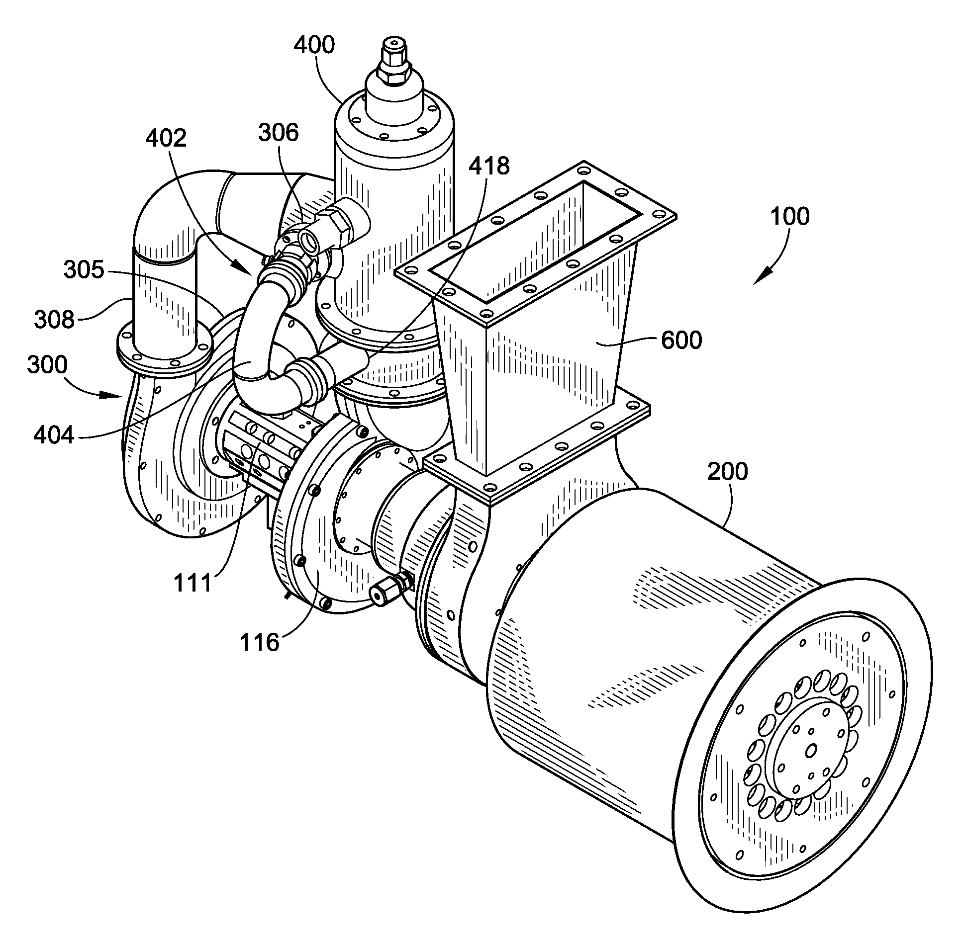
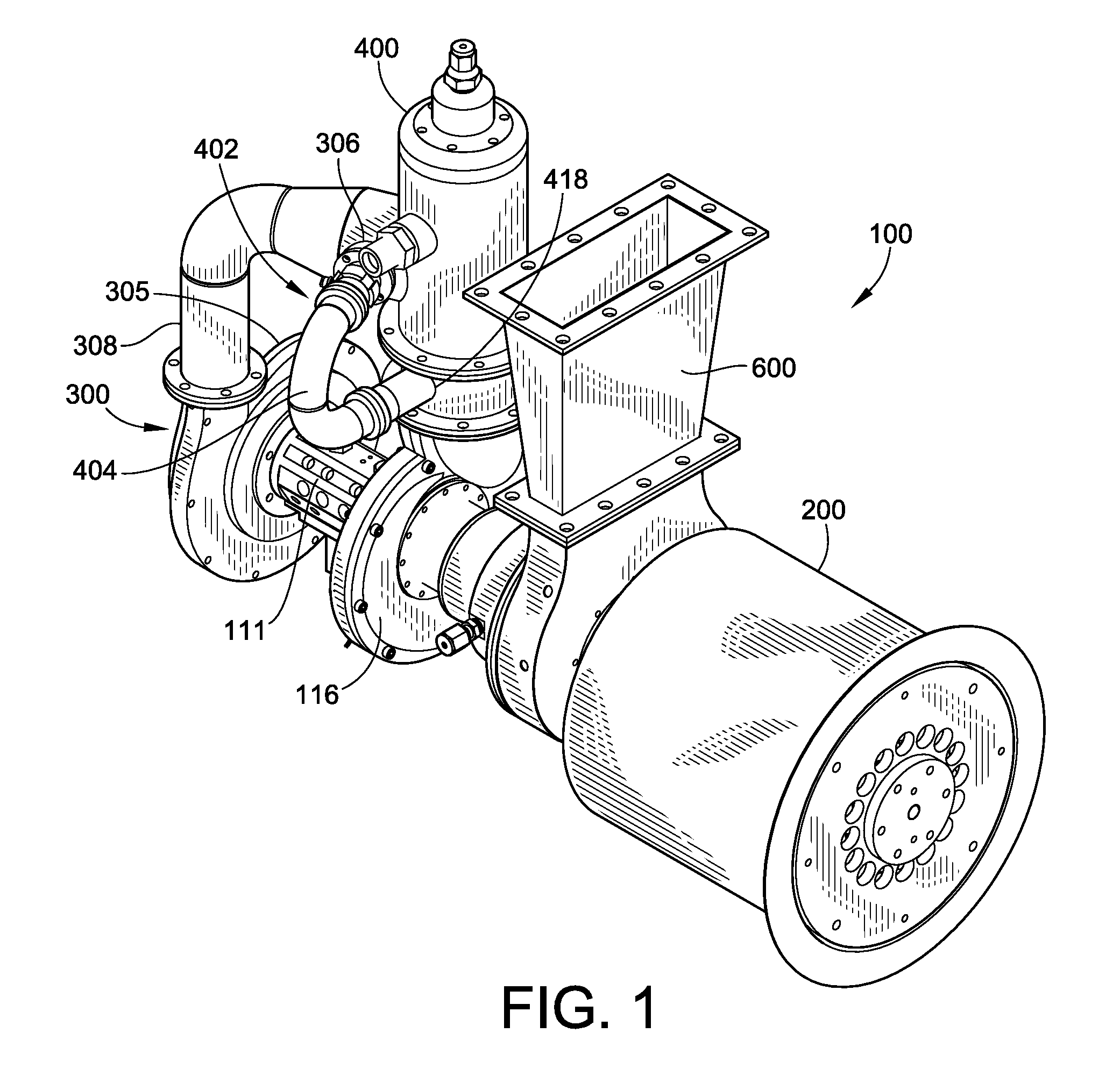
[0026]FIG. 1 is a perspective view illustrating the microturbine 100 in combination with a generator 200 of the present invention. The perspective view shows the following component parts of the micro gas turbine generator system:

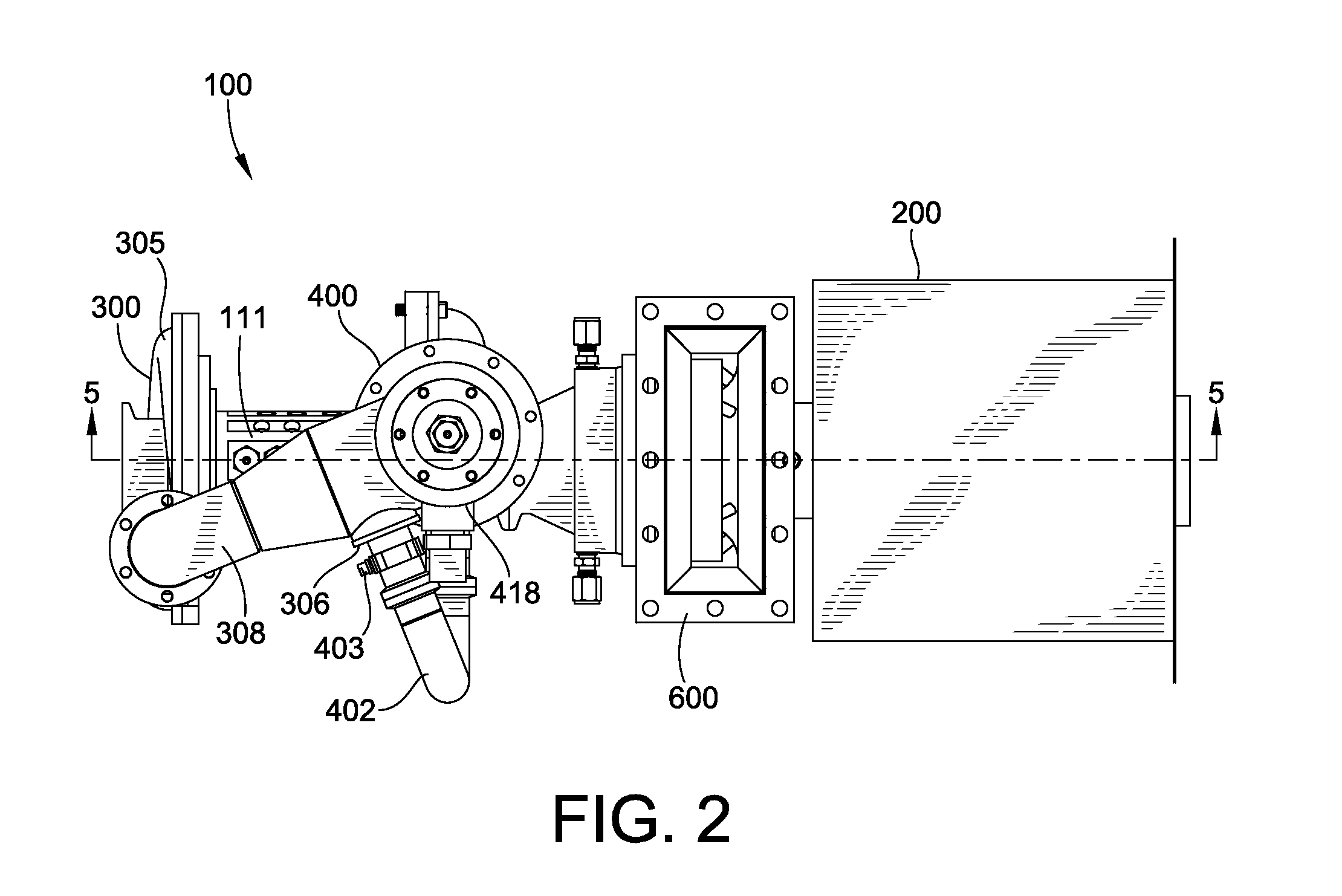
[0027]As illustrated in FIGS. 1-5, the microturbine engine (or “microturbine 100”) of the present invention includes a single or multi-stage compressor 300, a prevaporizing combustor 400 for liquid and / or gaseous fuels, a single or multi-stage gas generator turbine 112, and a gas generator shaft 105 supported by a bearing system 110 housed within a bearing tunnel 111. The microturbine 100 further includes a single or multi-stage power turbine 109 and a power output shaft 206 supported by a bearing system 210, 212. Typically, the gas turbine 100 is integrated with an electric generator 200 and / or heat recovery or generator cooling system 500. The systems also generally include a housing 102 and power and control electronics known to the art.

The Centrifugal C...


PUM


Abstract

A unique, small microturbine engine adapted to integrate with an electrical generator for producing electrical power has been developed. The microturbine includes an ejector cooling scheme, a prevaporizing combustor, and a combustor air bypass. The ejector cooling scheme uses energy in the hot exhaust gas stream of the microturbine to entrain a flow of ambient air that cools the generator. The prevaporizing combustor of the present invention allows liquid fuel to be vaporized in a small amount of air prior to combustion, thereby increasing combustion efficiency and decreasing combustor size requirements. The combustor air bypass allows a fraction of the compressor discharge air to bypass the prevaporizing combustor under certain operating conditions. This permits control of the overall equivalence ratio and the fuel / air mixing process in the combustion zone, improving efficiency and operability.

Description

CROSS-REFERENCE TO RELATED APPLICATION[0001]The application claims priority to U.S. Provisional Application entitled “MICRO GAS TURBINE ENGINE FOR POWERING A GENERATOR,” Ser. No. 61 / 769,501, filed Feb. 26, 2013, which is incorporated herein by reference in its entirety.FIELD OF THE INVENTION[0002]The present invention is directed to a small microturbine engine adapted to integrate with an electrical generator in such a way as to make a highly efficient, compact system.BACKGROUND[0003]A microturbine engine (or “microturbine”) is a type of combustion turbine engine that produces both heat and power on a relatively small scale. The component common to all microturbines is a small gas turbine engine, typically producing less than 500 kilowatts (kW) of power. This type of gas turbine comprises a single or multi-stage compressor, a combustor for liquid and / or gaseous fuels, a single or multi-stage turbine, and a power output shaft supported by a bearing system. Typically, the gas turbine ...

Claims


Application Information

Patent Timeline
Patent Type & Authority Applications(United States)
IPC IPC(8): F02C7/224F02C6/00H02K7/18F02C3/00
CPCF02C7/224H02K7/1823F02C6/00F02C3/00F23R3/30F23D11/105F23D11/445F23D11/448F05D2250/82F23C2900/03001F23R2900/03041F01D15/10H02K9/04
Inventor PERRY, MATTHEW V.FARINA, JORDAN T.LEPERA, STEPHEN D.FERRAR, ANTHONY M.O'BRIEN, WALTER F.SHIVER, SAMUEL
Owner ELECTRIC JET
Why Eureka
Try Eureka