Ultrasound probe and ultrasound diagnostic device

An ultrasonic and diagnostic device technology, applied in ultrasonic/sonic/infrasonic diagnosis, sonic diagnosis, infrasonic diagnosis, etc., can solve problems such as loss of image quality

Active Publication Date: 2013-05-01
TOSHIBA MEDICAL SYST CORP
View PDF13 Cites 6 Cited by
  • Summary
  • Abstract
  • Description
  • Claims
  • Application Information

AI Technical Summary

Problems solved by technology

Among other tradeoffs, image quality is sometimes compromised due to a lack of stable power in one of the image processing circuits

Method used


Image

  • Ultrasound probe and ultrasound diagnostic device
  • Ultrasound probe and ultrasound diagnostic device
  • Ultrasound probe and ultrasound diagnostic device

Examples


Embodiment Construction

[0028] The ultrasound imaging system according to this embodiment includes a probe or a converter unit, a processing unit, and a cable connecting the probe and the processing unit. In general, the embodiments of the probe include some structures, constituent elements, and elements of conventional ultrasonic probes. That is, in one embodiment of the probe, ultrasonic pulses are generated and transmitted to a certain area of ​​the patient. Reflected ultrasound echoes from the patient are also received in this embodiment. Many embodiments of the probe are generally connected to the processing unit via a cable and a handheld device, but the implementation of the probe according to this embodiment is not limited to these components.

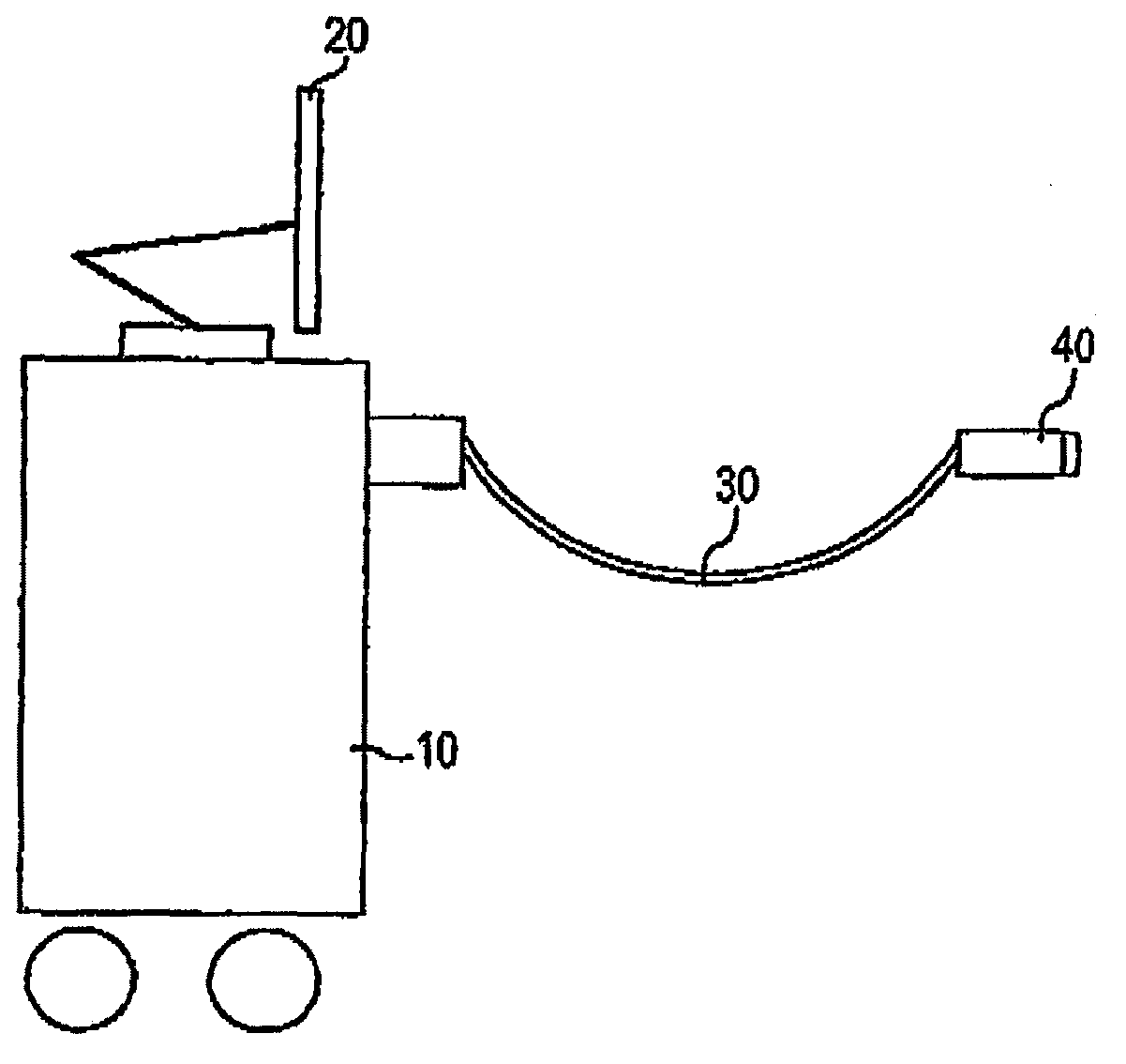
[0029] Such as figure 1 As shown, an embodiment of the ultrasound imaging system includes a system unit 10 , a cable 30 , and an ultrasound probe handle 40 . Probe 40 is connected to system 10 via cable 30 . The system unit 10 typically controls a...


PUM


Abstract

In general, embodiments of the ultrasound imaging system save power in relation to a predetermined active aperture and or a predetermined update depth. With respect to a predetermined active aperture, the imaging system saves power by reducing or turning off a predetermined portion of the receive electronics when the predetermined receive electronics portion is not operating in relation to the active aperture range. That is, in a first power saving mode, the predetermined receive electronics portion operates only when it is collecting and or processing the data inside the active aperture range. Furthermore, with respect to a predetermined update depth, the imaging system saves power by reducing the operational frequency as the predetermined receive electronics portion collects or process the data from a deeper area. That is, in a second power saving mode, the predetermined receive electronics portion operates less frequently when it is collecting and or processing the data from the middle or far range than the near range. Lastly, the imaging system saves power by modifying the operation as the predetermined receive electronics portion collects or process the data depending upon the active aperture and or the update depth. That is, in a third power saving mode, the predetermined receive electronics portion operates at least less frequently when it is collecting and or processing the data from the outside the active aperture and or at a far update depth. In other words, the third power saving mode is a hybrid or combination of the first and second power saving modes.

Description

technical field [0001] An ultrasonic probe and an ultrasonic diagnostic device that realize power saving in ultrasonic diagnosis. Background technique [0002] In order to save power in an ultrasonic diagnostic imaging system and a method of operating the ultrasonic diagnostic imaging system, conventional attempts have been made to turn off a certain circuit or reduce power consumption when the circuit is operating. Such an attempt is based on turning off a circuit that is not required or does not operate at a certain stage of operation, or reducing the power consumption of such a circuit. If such a circuit with reduced power is required again in some other operating phase, the ultrasonic imaging system increases the power consumption of such a circuit to an operable level. Of course, power consumption is saved to some extent in such an attempt, but additional controls are required. [0003] Extra control sometimes comes with several trade-offs. For example, it sometimes ...

Claims


Application Information

Patent Timeline
Patent Type & Authority Applications(China)
IPC IPC(8): A61B8/00
CPCA61B8/4488G01S7/52034A61B8/56G01S7/52096
Inventor G·米勒
Owner TOSHIBA MEDICAL SYST CORP
Why Eureka
Try Eureka