
electrical connector

A technology of electrical connectors and conductive terminals, which is applied in the field of drainage structures, can solve problems such as difficult water discharge, and achieve the effect of avoiding the danger of electric shock

Inactive Publication Date: 2015-09-09
FOXCONN (KUNSHAN) COMPUTER CONNECTOR CO LTD +1
View PDF12 Cites 0 Cited by
  • Summary
  • Abstract
  • Description
  • Claims
  • Application Information

AI Technical Summary

Problems solved by technology

However, for such a design, if water enters the inside of

Method used


Image

  • electrical connector
  • electrical connector
  • electrical connector

Examples


Embodiment Construction

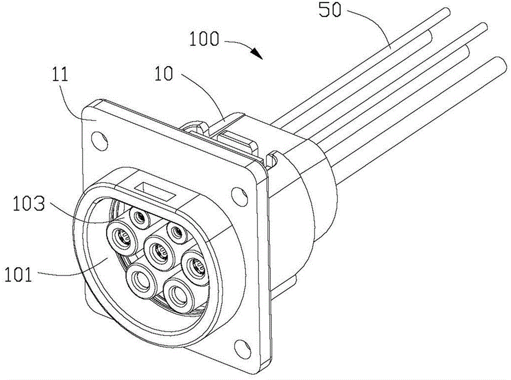
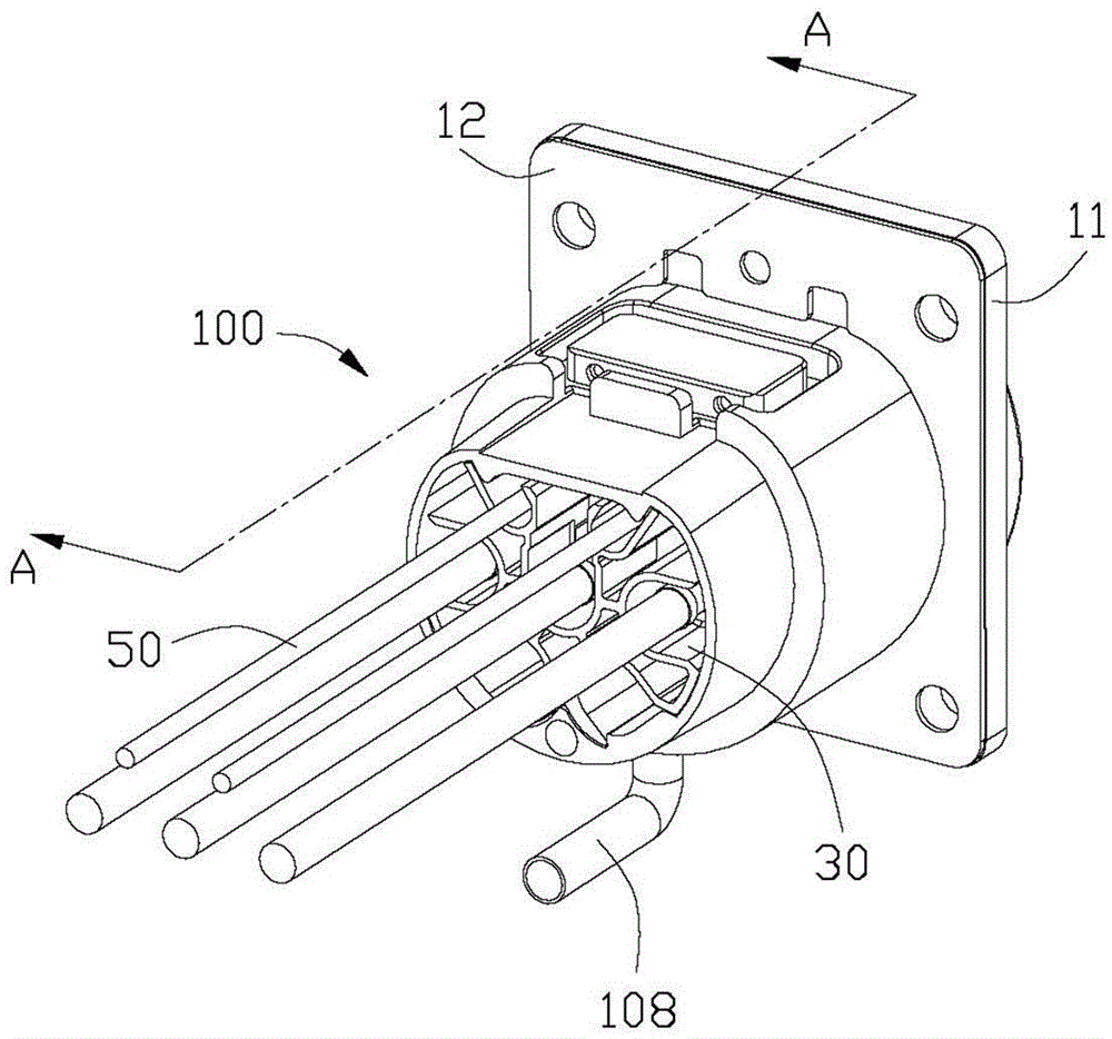
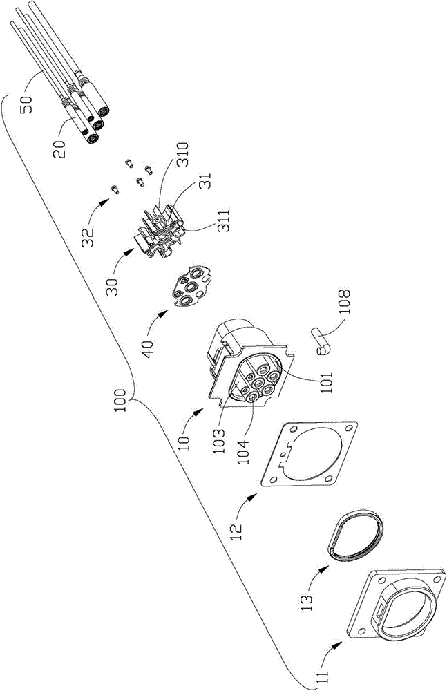
[0016] Such as Figure 1 to Figure 4 As shown, an electrical connector 100 includes an insulating body 10, a conductive terminal 20 accommodated in the insulating body 10, a holder 30 for holding the conductive terminal 20, a waterproof pad 40 installed at the rear end of the insulating body 10, and A cable 50 connected to the conductive terminal 20 . The electrical connector 100 also includes a socket port 11 that can be separated from the insulating body 10, a plastic pad 12 clamped between the insulating body 10 and the socket port 11, and a sealing ring installed on the insulating body 10 and the socket port 11. 13. Both the plastic pad 12 and the socket port 11 are provided with screw holes. When the insulating body 10 and the socket port 11 are assembled together by screws, since the plastic pad 12 has elasticity, the locking of the screws does not affect the electrical connector 100. will cause damage. When the electrical connector 100 is connected to the docking conn...


PUM


Abstract

Provided is an electric connector. The electric connector comprises an insulation body, and a conducting terminal housed in the insulation body, wherein the conducting terminal is provided with a blind hole used for housing a butt terminal. The bottom of the blind hole is provided with an opening which penetrates through the inner surface and the outer surface of the blind hole, water entering into the blind hole by accident is enabled to be discharged from the opening, and thereby the plugging function cannot be affected, and the emergence of electric shock hazard is avoid.

Description

technical field [0001] The invention relates to an electric connector, in particular to a drainage structure of the electric connector. Background technique [0002] For the prior art related to the invention, please refer to the published patent with publication number CN201690079. This published patent discloses an electrical connector, which includes an insulating body and conductive terminals accommodated in the insulating body. The bottom wall extends forward into the cylindrical part of the receiving space, and the cover located in front of the receiving space to cover the docking port of the insulating body, the cylindrical part is provided with an insertion port for the docking terminal to be inserted into the conductive terminal. However, with such a design, if water gets into the inside of the conductive terminal, it is difficult to drain the water. [0003] Therefore, it is necessary to design a new type of electrical connector to solve the above technical probl...

Claims


Application Information

Patent Timeline
IPC IPC(8): H01R13/52
Inventor 徐正华张金江吴立群
Owner FOXCONN (KUNSHAN) COMPUTER CONNECTOR CO LTD
Learn More