Electric welding device

A technology of connecting electricity and electric poles, which is applied in the direction of coupling devices, parts of connecting devices, circuits, etc., can solve problems such as poor protection ability, lack of protection devices, and no locking parts designed for plug connectors, so as to avoid electric shock hazards and improve Effects on Safety and Reliability

Inactive Publication Date: 2018-07-03
温岭市兴庆机械设备有限公司
View PDF0 Cites 0 Cited by
  • Summary
  • Abstract
  • Description
  • Claims
  • Application Information

AI Technical Summary

Problems solved by technology

[0002] At present, welding machines are used more and more widely, and they rely on the power supply connection to work normally. Therefore, whether the power supply connection of the welding machine is stable and the safety of the power supply connection is the basis for determining whether the welding machine can work normally. The power supply line of the machine is thick and heavy, and the p

Method used


Image

  • Electric welding device
  • Electric welding device
  • Electric welding device

Examples


Embodiment Construction

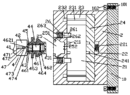
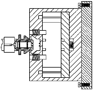
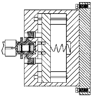
[0020] Such as Figure 1-Figure 5 As shown, an electric welding device of the present invention includes an electric connection base 2 and a plug part 4 arranged on the left side of the electric connection base 2, and the inside of the electric connection base 2 is provided with a cavity 21, and the cavity 21 The upper and lower sides are provided with first sliding grooves 23, and each of the first sliding grooves 23 is provided with a screw rod 231, the left end of the screw rod 231 is connected with the motor 232, and the cavity The inner wall on the right side of 21 is provided with a first slot 22, the inner wall on the left side of the cavity 21 is provided with a first connection rod 211, and the cavity 21 is provided with the upper and lower sides respectively entering the first In the sliding groove 23, the sliding block 24 that is slidingly fitted and connected, the sliding block 24 in the first sliding groove 23 is threadedly connected with the screw rod 231, and th...


PUM


Abstract

The invention discloses an electric welding device which comprises an electricity connection seat and a plug part arranged on the left side of the electricity connection seat; a cavity is formed in the electricity connection seat; first sliding grooves are formed in the upper side and the lower side of the cavity; a spiral rod is arranged in each first sliding groove; the left side ends of the spiral rods are connected with motors; a first slotted hole is formed in the inner wall of the right side of the cavity; first electricity connection rods are arranged at the inner wall of the left sideof the cavity; a sliding block is arranged in the cavity; the upper side and the lower side of the sliding block enter into the first sliding grooves in the upper side and the lower side of cavity andare connected with the first sliding grooves in a sliding fit manner; the parts, in the first sliding grooves, of the sliding block are connected with spiral threads of the spiral rods in a fit manner; first electrifying holes opposite to the first electricity connection rods are formed in the end face of the left side of the sliding block; a circuit is arranged between the end face of the left side of the sliding block and the first slotted hole; an inserting cavity is formed in a wall body on the left side of the electricity connection seat; and second electricity connection rods are arranged at the inner wall of the right side of the inserting cavity. The electric welding device is simple in structure and convenient and quick to operate, power supply connection can be controlled automatically, the inserting connection firmness and safety are relatively high, electric shock danger caused by accidental touch is prevented, and the power supply requirement of an existing welding machine is met.

Description

technical field [0001] The invention relates to the field of welding technology, in particular to an electric welding device. Background technique [0002] At present, welding machines are used more and more widely, and they rely on the power supply connection to work normally. Therefore, whether the power supply connection of the welding machine is stable and the safety of the power supply connection is the basis for determining whether the welding machine can work normally. The power supply line of the machine is thick and heavy, and the plug joint design of the welding machine is relatively simple and does not design any locking parts. The phenomenon of poor contact occurs, which has great disadvantages. At the same time, the existing socket setting mode matched with the plug connector is relatively simple, the protection ability is poor, and the protection device is lacking, so there is a large potential safety hazard. Contents of the invention [0003] The technical ...

Claims


Application Information

Patent Timeline
IPC IPC(8): B23K9/32H01R13/447H01R13/627
CPCB23K9/32H01R13/447H01R13/6273
Inventor 王丹
Owner 温岭市兴庆机械设备有限公司
Why Eureka
Try Eureka