Jig for detecting concentricity of jet nozzle

A technology for detecting jig and concentricity, applied in measuring devices, mechanical measuring devices, instruments, etc., can solve the problems of low utilization rate and low efficiency of measuring beds, and achieve time-saving, convenient detection, and friction reduction. Effect

Active Publication Date: 2013-06-05
马斯特模具有限公司
View PDF7 Cites 2 Cited by
  • Summary
  • Abstract
  • Description
  • Claims
  • Application Information

AI Technical Summary

Problems solved by technology

[0002] At present, the concentricity of the diameter of the flange and the front of the nozzle is required to be relatively h

Method used


Image

  • Jig for detecting concentricity of jet nozzle
  • Jig for detecting concentricity of jet nozzle
  • Jig for detecting concentricity of jet nozzle

Examples


Embodiment Construction

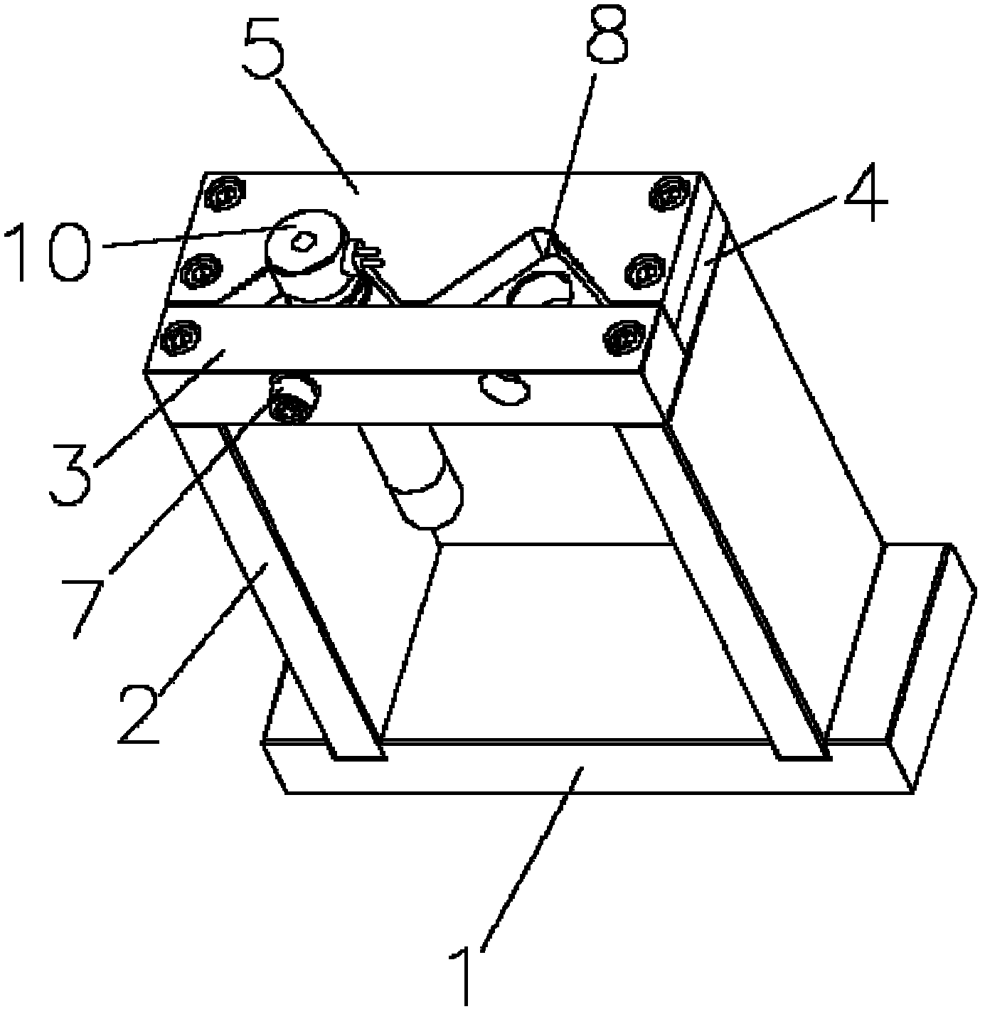
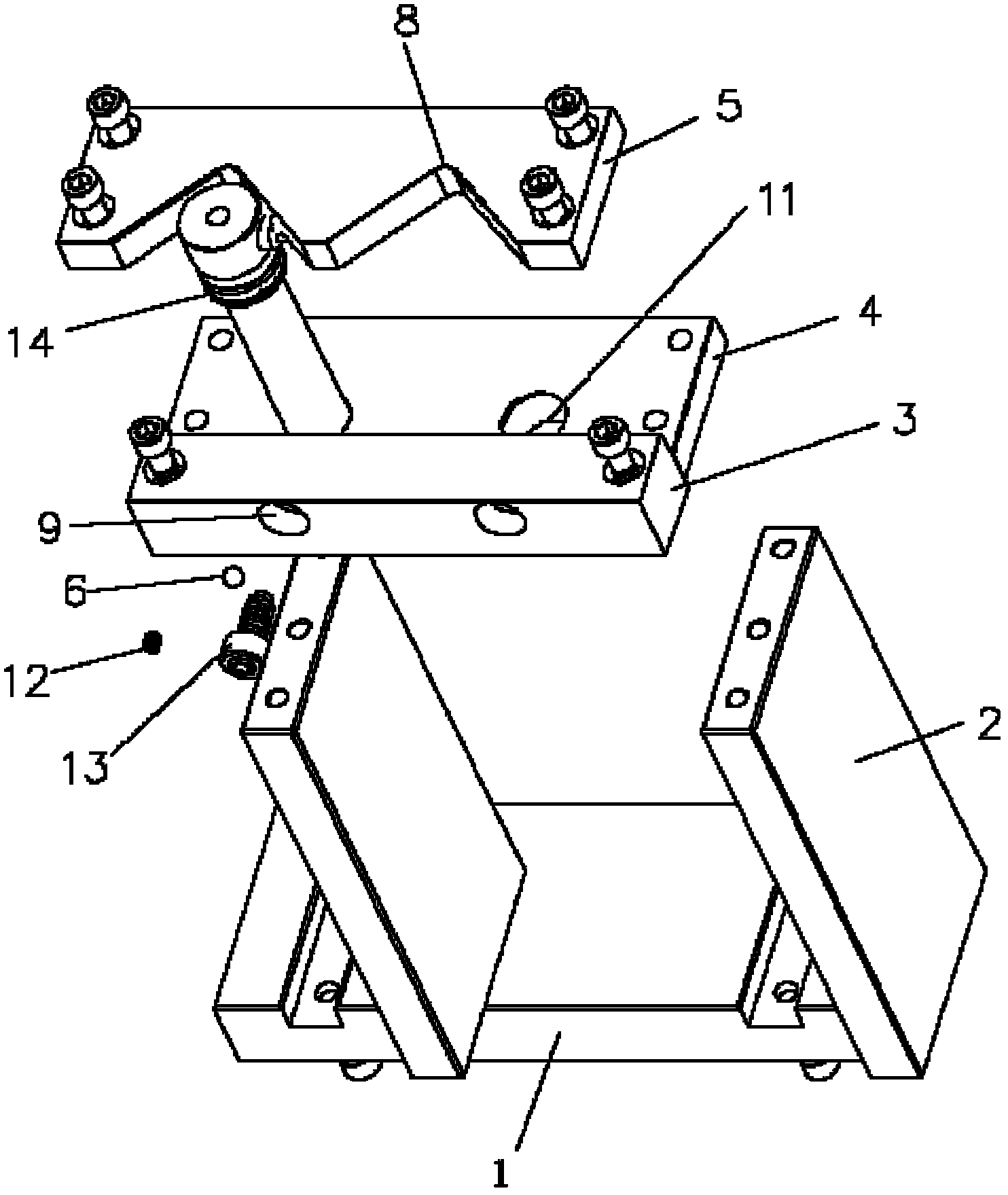
[0022] A nozzle concentricity detection jig, comprising a base plate 1, a support plate 2, a marble adjustment plate 3, a workpiece carrying plate 4, a positioning plate 5, a marble 6 and a pressing mechanism 7, the support plates are two pieces, and The interval is fixed above the base plate; the workpiece carrying plate is fixed above the two pillar plates; the marble adjustment plate is fixed on the upper side of the workpiece carrying plate, and the positioning plate is fixed on the The other side above the workpiece carrying plate; the positioning plate is provided with at least one V-shaped notch 8 near the end of the pinball adjusting plate, and a V-shaped notch is provided on the pinball adjusting plate facing the V-shaped notch. The through hole 9 that can just accommodate the marbles, and the pressing mechanism can just drive the marbles to move in the through hole; A workpiece hole 11 having a larger outer diameter than the nozzle 10 to be tested. When in use, one ...


PUM


Abstract

The invention discloses a jig for detecting concentricity of jet nozzle. The jig comprises a base plate, two abutment plates, a marble adjusting plate, a workpiece bearing plate, a positioning plate, a marble and a hold-down mechanism, the two abutment plates are fixedly arranged above the base plate at intervals, the workpiece bearing plate is fixedly arranged above the two abutment plates, the marble adjusting plate is fixedly disposed on one side above the workpiece bearing plate, the positioning plate is fixedly mounted on the other side above the workpiece bearing plate, one end of the positioning plate, which is close to the marble adjusting plate, is provided with at least one V-shaped notch, a through hole which rightly faces to the V-shaped notch and accommodates the marble is arranged on the marble adjusting plate, the hold-down mechanism rightly drives the marble to move in the through hole, and a position of the workpiece bearing plate, which rightly faces to the V-shaped notch, is provided with a workpiece hole in a size which is at least larger than the outer diameter of a jet nozzle to be detected. The jet nozzle concentricity detecting jig is simple in structure and high in efficiency.

Description

technical field [0001] The invention relates to a jig for detecting nozzle concentricity. Background technique [0002] At present, the concentricity of the diameter of the flange and the front of the nozzle is required to be relatively high (within 0.01mm). When measuring the size with this method, it must be measured on a three-dimensional measuring bed. Low. Contents of the invention [0003] In order to overcome the above defects, the present invention provides a nozzle concentricity detection jig, which not only has a simple structure, but also has high efficiency. [0004] The technical solution adopted by the present invention in order to solve the technical problem is: a nozzle concentricity detection fixture, including a base plate, a support plate, a pinball adjustment plate, a workpiece carrying plate, a positioning plate, a pinball and a pressing mechanism, the There are two pillar plates, which are fixed above the base plate at intervals; the workpiece carry...

Claims


Application Information

Patent Timeline
IPC IPC(8): G01B5/252
Inventor 安凌
Owner 马斯特模具有限公司
Why Eureka
Try Eureka