Wireless transmission method, wireless transmitter and wireless receiver

A wireless receiver and wireless transmission technology, applied in the field of wireless transmission methods, wireless transmitters and wireless receivers, can solve the problems of poor reception quality, degradation of demodulation processing capability, degradation of throughput characteristics, etc., and achieve high throughput characteristics , the effect of avoiding the deterioration of separation performance

Active Publication Date: 2013-06-12
FUJITSU LTD
View PDF1 Cites 0 Cited by
  • Summary
  • Abstract
  • Description
  • Claims
  • Application Information

AI Technical Summary

Problems solved by technology

[0016] Here, in the prior art described above, the number of beams to be formed is constant (for example, fixed to the maximum number of beams that can be formed) regardless of the number of transmission streams (in other words, the beam width per beam (directivity Intensity) constant), so the effect of MIMO multiplexing cannot be obtained through the selected beam, resulting in the degradation of throughput characteristics
[0017] For example, based on the feedback information from the receiving side, if beams with high correlation (for example, mutually adjacent beams) are selected on the transmitting side, it will result in separation of user data streams on the receiving side, demodulation processing Capability deterioration
Therefore, as long as the beam with low correlation degree is boldly selected, the separation and the deterioration of the demodulation processing capability can be suppressed. gain) the reception quality of a beam with good beam selection is poor
[0018] Here, as described in the above-mentioned Patent Document 1, if the signal matrix or reception weight used by the receiving side is fed back to the transmitting side as the feedback information, it is possible to adjust and select inter-beam correlation or beam directivity, and it is possible to alleviate the problem. The above-mentioned separation, degradation of demodulation processing capability, or degradation of reception quality leads to an increase in the amount of feedback information, and calculation processing is required for adjustment

Method used


Image

  • Wireless transmission method, wireless transmitter and wireless receiver
  • Wireless transmission method, wireless transmitter and wireless receiver
  • Wireless transmission method, wireless transmitter and wireless receiver

Examples


Embodiment Construction

[0054] Hereinafter, embodiments of the present invention will be described with reference to the drawings.

[0055] [A] Summary

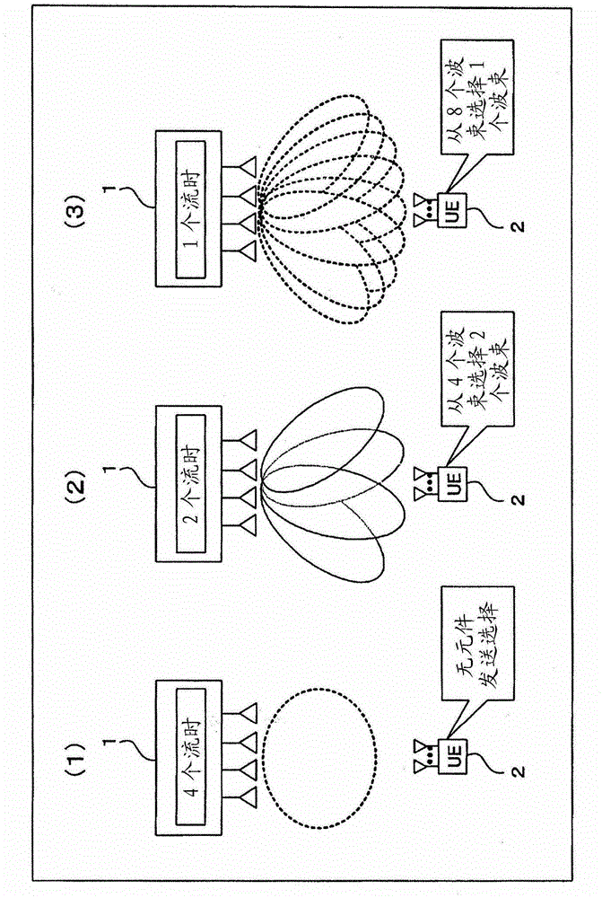
[0056] First, use figure 1 , the outline of the embodiment to be described below will be described. Should figure 1 Among them, 1 represents a MIMO transmitter with multiple (here, 4) transmit antennas, and 2 represents a MIMO receiver with multiple receive antennas, and wireless communication can be used between these MIMO transmitter 1 and MIMO receiver 2 Perform MIMO transmission. In addition, the MIMO transmitter 1 can be applied, for example, as a base station apparatus of a mobile radio communication system, and the MIMO receiver 2 can also be applied as a mobile station apparatus (UE: User Equipment) of the system. Therefore, in the following description, the MIMO transmitter 1 may be expressed as the base station device 1 or the base station 1 , and the MIMO receiver 2 may be expressed as the mobile station device 2 or the mobile stati...


PUM


Abstract

The invention provides a wireless transmission method, a wireless transmitter and a wireless receiver. According to the wireless transmitter (1), the number of sent beams is controlled according to the number of data flows which should be transmitted, wherein the number of the sent beams is formed by transmitting the data flows. The wireless receiver (2) is used for selectively receiving at least one arbitrary sent beam of the sent beams. Through changing the formed number of the sent beams according to the number of the transmitted data flows in such a manner, the high throughput feature based on relevancy among low beams when multi-flow transmission is performed and high directional gain when single-flow transmission is performed can be realized.

Description

[0001] This application is the original application of the application date of February 2, 2006, the application number is 200680052201.X (international application number PCT / JP2006 / 301776), and the title of the invention is "wireless transmission method, wireless transmitter and wireless receiver" Divisional application. technical field [0002] The present invention relates to a wireless transmission method, a wireless transmitter, and a wireless receiver, and particularly relates to a wireless transmission technology suitable for use in multiple input and multiple output wireless transmission technologies that use multiple transceiver antennas for signal transmission in wireless communication systems such as mobile phones and wireless access. technology. Background technique [0003] In recent years, MIMO (Multiple-Input Multiple-Output: Multiple-Input Multiple-Output: Multiple-Input Multiple-Output) has been attracting attention as a technology that enables large-capaci...

Claims


Application Information

Patent Timeline
Patent Type & Authority Applications(China)
IPC IPC(8): H04B7/06H04B7/04
Inventor 筒井正文关宏之
Owner FUJITSU LTD
Why Eureka
Try Eureka