Rope buckle

A rope buckle and rope technology, applied in the field of rope buckles, can solve the problems of labor, unsmooth travel, relative displacement of rope D, etc., and achieve the effect of certain positioning loose or slipping, not easy to loosen or slipping, and the rope is firmly held.

Active Publication Date: 2015-07-08
NIFCO TAIWAN
View PDF10 Cites 0 Cited by
  • Summary
  • Abstract
  • Description
  • Claims
  • Application Information

AI Technical Summary

Problems solved by technology

[0004] Therefore, it can be known from the above that the known rope buckle utilizes the fastening part C1 of the push part C and the buckle hole B11 of the elastic positioning part B for a movable docking, and can be pushed on the push part C to drive the displacement of the slider B1, so that the slider B1 can tightly clamp the rope D through the elastic displacement of the elastic body B3. The way that the pushing part C directly drives the displacement of the slider B1 is prone to deflection, so that the rope D in the second hole A11 cannot be evenly stressed. When the rope D is pulled by different external forces, it will cause the blockage between the slider B1 and the base A, resulting in an increase in the failure rate and damage, or the relative displacement of the rope D, which may also cause the slider B1 and the rope D to be excessively stuck. It is not easy to loosen, so that the displacement stroke of the sliding block B1 and the elastic body B3 driven by the pushing part C is not smooth and laborious, and affects the stability and smoothness of the overall operation, and it needs to be redesigned by those engaged in this industry. be effectively resolved

Method used


Image

  • Rope buckle
  • Rope buckle
  • Rope buckle

Examples


Embodiment Construction

[0065] The technical means and its structure used in the present invention are described in detail in conjunction with the accompanying drawings for the preferred embodiments of the present invention. The structure and function are as follows for complete understanding.

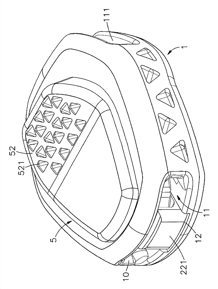
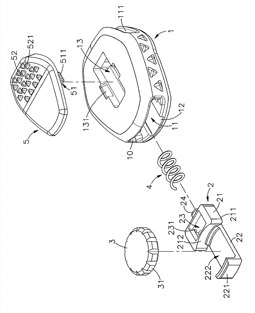
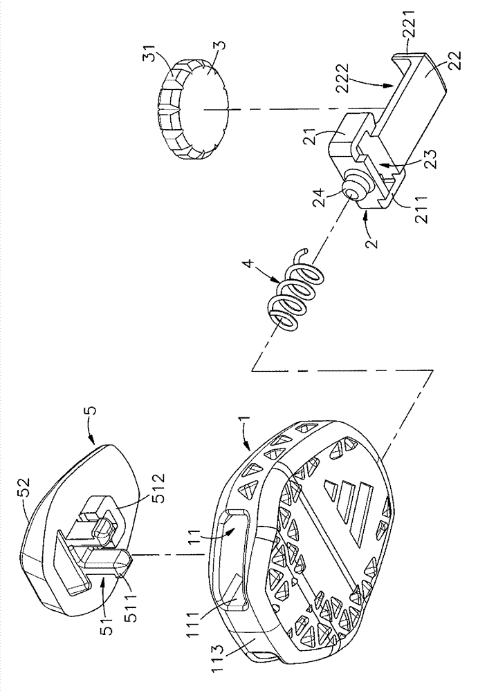
[0066] see figure 1 , figure 2 , image 3 , Figure 4 As shown, they are respectively the three-dimensional appearance diagram, the three-dimensional exploded view, the three-dimensional exploded view of another angle of view and the side sectional view of the present invention. It can be clearly seen from the figure that the present invention includes a seat body 1 and a sliding seat 2. , positioning body 3, elastic component 4 and outer cover 5, so the main components and features of this case are described in detail as follows, wherein:

[0067] This seat body 1 can be a hollow accommodation body, and its hollow interior is horizontally formed with available rope 6 (such as Figure 5 shown) through t...


PUM


Abstract

Provided is a rope buckle. A channel capable of containing a sliding base is formed in a base body, through holes are formed in wall faces at two sides of the channel, an elastic assembly is located between the base body and the sliding base, a sliding part located in a guide rail at the bottom of the channel extends outward from the bottom of the sliding base, and a locating body is contained in a bearing groove formed in the sliding part. When a rope penetrates through the inside of the channel, an outer cover on the base body can be pushed so that a locating column on the bottom face of the outer cover drives the sliding base to move in the channel in a reciprocating, the rope penetrates out of the through holes and is released in the outer cover, and therefore the sliding base drives the locating body to move synchronously through elastic reset force of the elastic assembly, and is meshed with the rope through the fact that a preset distance formed by a plurality of clamping parts on the circumference of the locating body and the channel decreases. Therefore, the effects that the rope is fixed and clamped firmly, precise in locating and not prone to loosen or slide out of the base body are achieved.

Description

technical field [0001] The invention provides a rope buckle, especially an outer cover that can push the seat on the top to drive the sliding seat to reciprocate and slide inside the passage, and pass the rope through the perforation holes on both sides of the passage to pass through the elasticity of the elastic component. The reset force makes the sliding seat drive the positioning body to displace synchronously, and the plurality of clamping parts at the periphery of the positioning body are engaged with the rope, so as to achieve the effect of firm holding of the rope and accurate positioning. Background technique [0002] Press, the use of buckles is very common nowadays, and different types of buckles have different fastening methods, and can be applied to shoes, bags or clothes at the same time, and buckles are usually threaded inside them by using ropes , and put the head of the two ends of the rope out, then a buckle can be used to insert the outer diameter of the h...

Claims


Application Information

Patent Timeline
Patent Type & Authority Patents(China)
IPC IPC(8): A44B11/06
Inventor 萧勋名张马克菲力克斯·施托比策
Owner NIFCO TAIWAN
Why Eureka
Try Eureka