Optical fiber ear and nose cavity mirror

An optical fiber and nasal cavity technology, applied in the field of ear and nose detection equipment, can solve the problems of high cost, image distortion, and inconvenience for doctors to use, and achieve the effects of reducing manufacturing cost, reducing image distortion, and facilitating observation

Inactive Publication Date: 2015-05-20
上海晋通光学科技有限公司
View PDF10 Cites 0 Cited by
  • Summary
  • Abstract
  • Description
  • Claims
  • Application Information

AI Technical Summary

Problems solved by technology

However, this existing optical system is not only complicated in structure and serious in image distortion, but also requires high cost. In addition, because it uses multiple optical lenses, it is impossible to make the protective tube very thin (the ear tubes currently on the market The minimum diameter of the rigid tube scope of the rhinoscope is 6mm), which causes inconvenience to the doctor's use and also brings discomfort to the patient

Method used


Image

  • Optical fiber ear and nose cavity mirror
  • Optical fiber ear and nose cavity mirror

Examples


Embodiment Construction

[0029] Below in conjunction with the drawings, preferred embodiments of the present invention are given and described in detail.

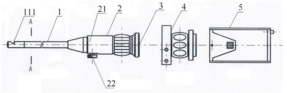
[0030] like figure 1 , 2 Shown, the present invention, that is, a kind of fiber optic otolaryngoscope, it comprises the rigid tube mirror 1, image amplifier 2, eyepiece 3, photoelectric converter 4 and CCD image sensor 5 that are connected coaxially successively, wherein, image amplifier 2 comprises An amplifier body 21 and an image adjustment knob 22 are connected to each other.

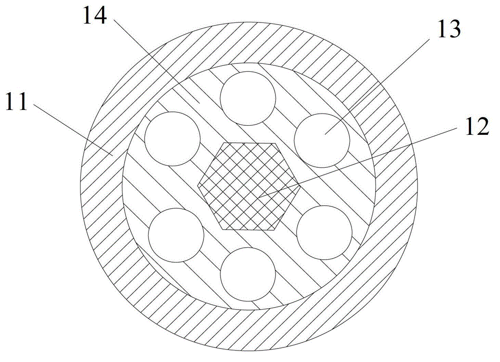
[0031] The rigid tube mirror 1 among the present invention comprises:

[0032] A protective tube 11, the outer edge of the protective tube 11 is provided with a photometric hole 111, and the position of the photometric hole is close to the end of the protective tube 11 away from the eyepiece 3;

[0033] One is used to transmit the image to the image amplifier 2 and finally to the image transmission fiber filament 12 of the eyepiece 3, and the image transmission fiber ...


PUM


Abstract

The invention relates to an optical fiber ear and nose cavity mirror which comprises a rigid tube mirror and an eye lens. The rigid tube mirror and the eye lens are coaxially arranged in sequence. The rigid tube mirror comprises a protective tube, an image transmission optical fiber wire and a plurality of light transmission optical fiber wires, wherein a light measuring hole is formed in an outer edge of the protective tube, the image transmission optical fiber wire is used for transmitting an image to the eye lens and is fixedly arranged in the protective tube in a homocentric mode, the light transmission optical fiber wires are used for receiving light rays of peripheral light sources through the light measuring hole, the plurality of light transmission optical fiber wires and the image transmission optical fiber wire are fixedly arranged in the protective tube in parallel and the plurality of light transmission optical fiber wires are evenly distributed around the image transmission optical fiber wire and are separated from the image transmission optical fiber wire. The image transmission optical fiber wire serves as an optical fiber element for transmitting the image, 'zero' thickness performance of an image transmission element is completely used and the plurality of light transmission optical fiber wires are adopted in a matched mode so that the image can be transmitted to the eye lens clearly, image distortion is greatly reduced, structure is simplified and manufacture cost is reduced.

Description

technical field [0001] The invention relates to an ear and nose detection device, in particular to an optical fiber otoloscope. Background technique [0002] At present, in the diagnosis process of ear, nose and throat diseases, the detection equipment usually used is otoloscope. The optical system in the conventional ENT mirror includes a plurality of refractable optical lenses arranged in the protective tube of the rigid tube mirror, through the combination of these optical lenses, the image can be transmitted to the eyepiece in the ENT mirror for observation. However, this existing optical system is not only complicated in structure and serious in image distortion, but also requires high cost. In addition, because it uses multiple optical lenses, it is impossible to make the protective tube very thin (the ear tubes currently on the market The minimum diameter of the rigid tube scope of the rhinoscope is 6mm), which causes inconvenience to the doctor's use and also brings...

Claims


Application Information

Patent Timeline
Patent Type & Authority Patents(China)
IPC IPC(8): A61B1/227A61B1/233A61B1/07A61B1/04
Inventor 王根海赵惠民杨先贵
Owner 上海晋通光学科技有限公司
Why Eureka
Try Eureka