Compression roller of splitting machine rewinding shaft

A technology of winding shaft and slitting machine, which is applied in the direction of winding strips, thin material processing, transportation and packaging, etc. It can solve the problems affecting the appearance and quality of products, and achieve the effect of improving appearance and quality

Inactive Publication Date: 2013-06-19
深圳市宜美特科技有限公司
View PDF5 Cites 2 Cited by
  • Summary
  • Abstract
  • Description
  • Claims
  • Application Information

AI Technical Summary

Benefits of technology

This technology helps creating better products with less waste material when producing them through methods like slotting or trimming edges on blinds during production processes. By pressing harder against an existing blade surface instead of just rolling it over itself, this process results in fewer defects that can be detected later.

Problems solved by technology

This patented technical problem addressed in this patents relates to improving the smoothness and uniform thickness of thin films during production processes such as lithography machines. Specifically, there may occur issues with maintaining proper alignment between two parts called the moving parts for example cylindrical bearings within the machine's housing. Additionally, certain types of coatings like silicone rubber require specific conditions for effective use over time without losing effectiveness.

Method used


Image

  • Compression roller of splitting machine rewinding shaft
  • Compression roller of splitting machine rewinding shaft

Examples


Embodiment Construction

[0021] Below in conjunction with accompanying drawing and embodiment the present invention is further described:

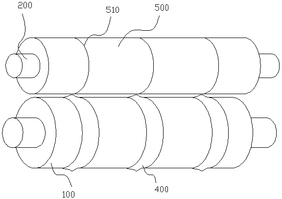
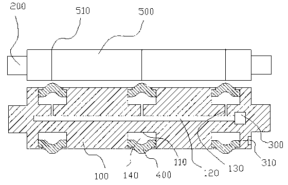
[0022] figure 1 It is a schematic diagram of the axonometric structure of an embodiment of the rewinding shaft pressure roller of the slitting machine, figure 2 It is the rewinding shaft pressure roller of the slitting machine figure 1 The structural representation of the embodiment, in order to illustrate the problem, will now figure 1 , figure 2 The present invention is explained as the same embodiment.

[0023] In this embodiment, the slitting machine winding shaft pressure roller includes a pressing roller 100, which is arranged parallel to the slitting machine winding shaft 200, and the pressing roller 100 is close to the product 500 on the winding shaft 200, The pressure roller 100 is provided with a groove 110 corresponding to the slit 510 of the cut product 500, and a rubber ring 400 matching it is arranged in the groove 110, and the rubber ring 400 ...


PUM


Abstract

The invention provides a compression roller of a splitting machine rewinding shaft which comprises the compression roller, wherein the compression roller is arranged parallel to the splitting machine rewinding shaft, the compression roller is close tightly to products on the rewinding shaft, a groove corresponding to a lancing of the split product is installed on the compression roller, a rubber ring matched with the groove is installed inside the groove, the rubber ring forms a embossment on the surface of the compression roller, an upheaval on the edge of the lancing of the split product is compressed by the embossment of the rubber ring, because the edge of the lancing of the compressed product receives a bigger stress than that of a normal compression roller, the edge of the lancing of the product has the flatter edge of the lancing so as to improve appearance and quality of the products.

Description


Claims


Application Information

Patent Timeline
Owner 深圳市宜美特科技有限公司
Why Eureka
Try Eureka