In-mould automatic-shearing pouring gate mechanism

A gate, automatic technology, applied in the field of automatic shear gate mechanism in the mold, can solve the problems of wasting manpower and equipment, and the cutting place is not beautiful, and achieves the effect of beautiful cutting and cutting, saving manpower and equipment costs.

Inactive Publication Date: 2013-06-26
SUZHOU MITAC PRECISION TECH
View PDF4 Cites 4 Cited by
  • Summary
  • Abstract
  • Description
  • Claims
  • Application Information

AI Technical Summary

Problems solved by technology

[0004] In order to solve the above problems, the object of the present invention is to provide an automatic in-mold shearing gate mechanism to overcome the need for follow-up manual or jigs to cut the gate in the prior art, which wastes manpower and equipment, and the cutting place is not beautiful enough. Defects and deficiencies

Method used


Image

  • In-mould automatic-shearing pouring gate mechanism
  • In-mould automatic-shearing pouring gate mechanism
  • In-mould automatic-shearing pouring gate mechanism

Examples


Embodiment Construction

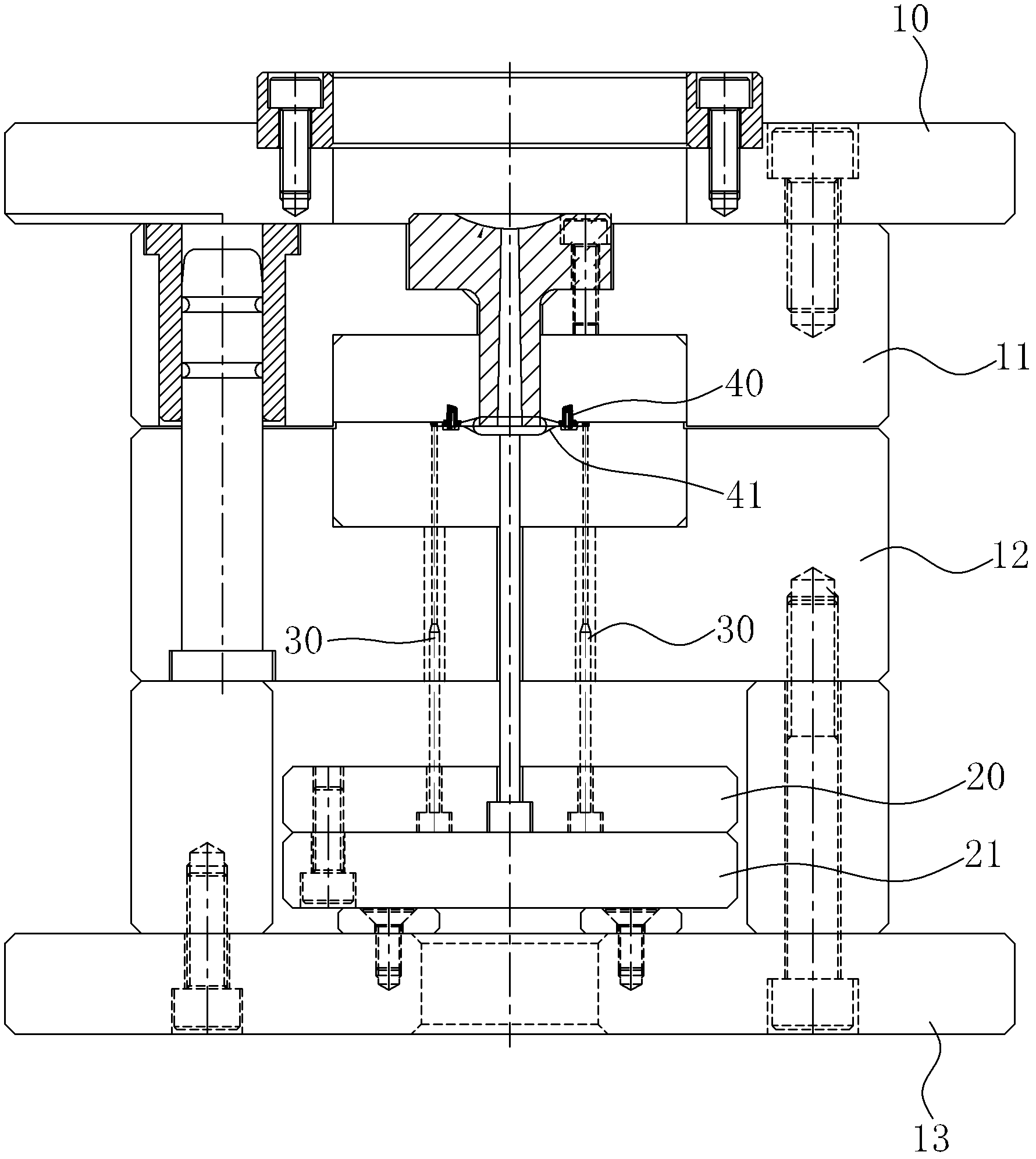
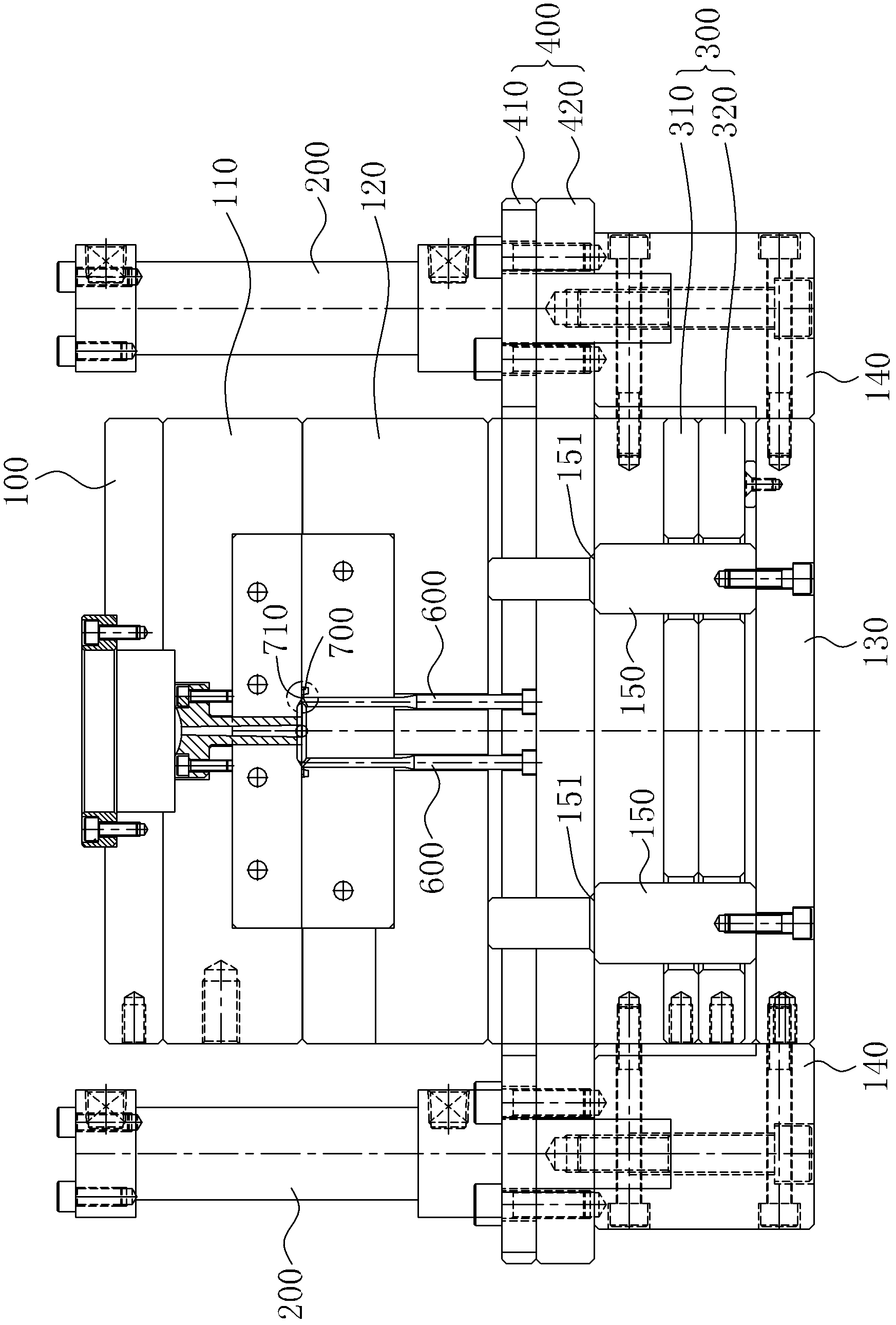
[0018] see figure 2 , image 3 As shown, the in-mold automatic shearing gate mechanism of the present invention is applied in a mould. state, the automatic shear gate mechanism in the mold includes:

[0019] Hydraulic cylinder 200, which is located on both sides of the mold and is fixedly connected with the foot pads 140 on both sides of the mold by screws;

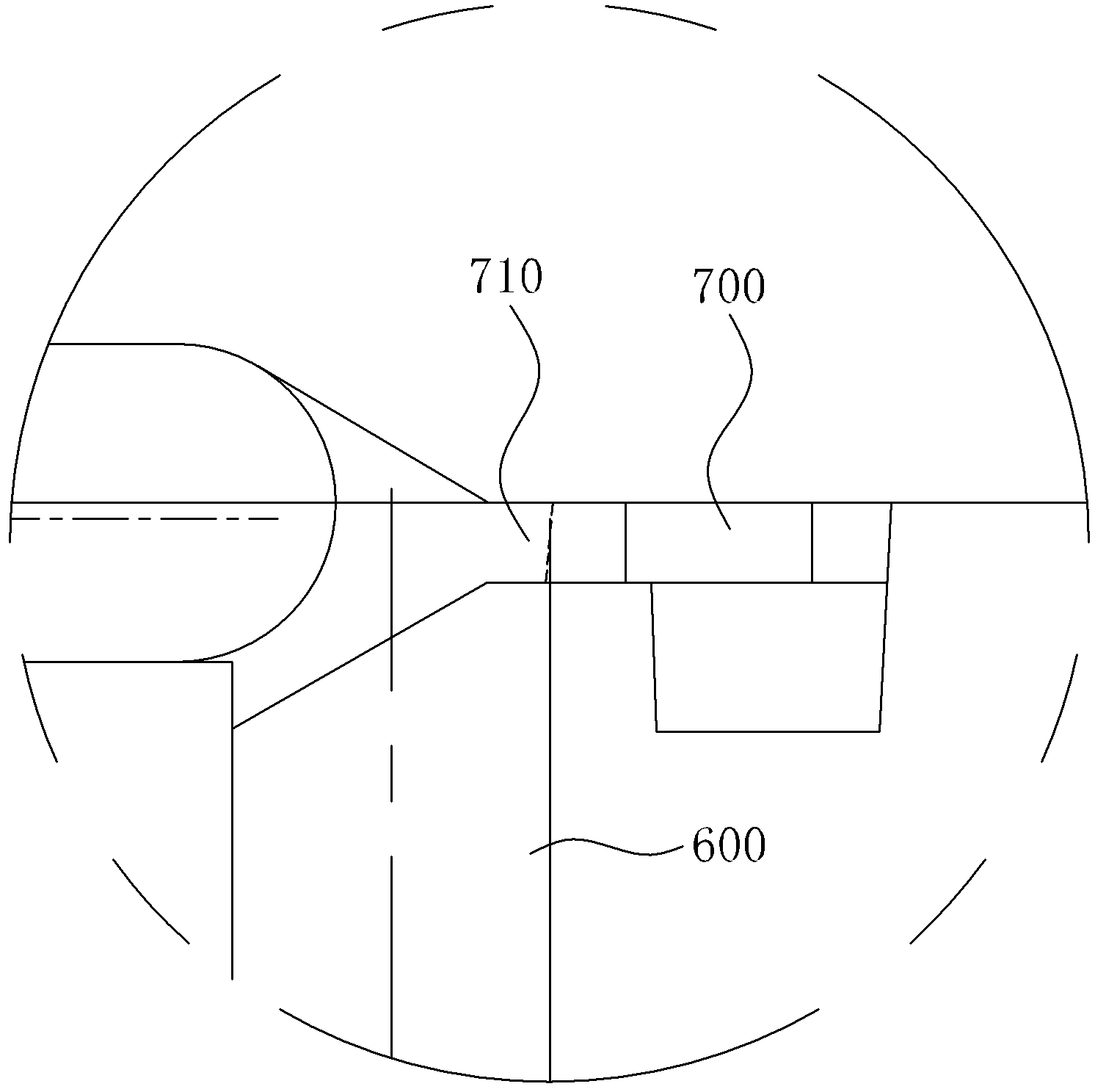
[0020] The first ejector plate 300, which is located above the lower fixing plate 130, the first ejector plate 300 includes a first upper ejector plate 310 and a first lower ejector plate 320, and on the first ejector plate 300 An ejector pin is fixed to eject the product 700;

[0021] The second ejector plate 400 is located above the first ejector plate 300, the second ejector plate 400 is connected to the hydraulic cylinder 200, the second ejector plate 400 includes a second upper ejector plate 410 and The second lower ejector plate 420, the hydraulic cylinder 200 drives the second ejector plate 400 to eject and re...


PUM


Abstract

The invention relates to an in-mould automatic-shearing pouring gate mechanism applied into a mould. The in-mould automatic-shearing pouring gate mechanism comprises an oil cylinder, a first ejector plate, a second ejector plate and a pouring gate cutting needle, wherein the oil cylinder is arranged on the two sides of a mould and is fixedly connected with a foot pad; the first ejector plate is arranged above a lower fixing plate and comprises a first upper ejector plate and a first lower ejector plate, and the first ejector plate is provided with an ejector pin which is used for ejecting products; the second ejector plate is arranged above the first ejector plate, is connected with the oil cylinder and comprises a second upper ejector plate and a second lower ejector plate, and the oil cylinder drives the second ejector plate to eject and return; and one end of the pouring gate cutting needle is arranged in the second ejector plate, and the other end of the pouring gate cutting needle is contacted with a pouring gate. According to the in-mould automatic-shearing pouring gate mechanism disclosed by the utility model, no cutting action is required after the product is ejected, so that the manpower and equipment costs are saved, and the cut and sheared parts of the product and the pouring gate are relatively beautiful.

Description

【Technical field】 [0001] The invention relates to a shear gate mechanism, in particular to an automatic shear gate mechanism in a mold. 【Background technique】 [0002] In the plastic mold manufacturing industry, there are more and more plastic products for appearance parts. The requirements for this kind of appearance parts are very strict. There must be no joint lines, flow marks, burrs, gates, etc. Manufacturing puts forward higher requirements. [0003] After the product is injection molded in the mold production, there is still a gate on the product, such as a lap gate or a side gate. see figure 1 As shown, it is a schematic diagram of a mold mechanism in the prior art. This existing mold mechanism comprises: upper fixed plate 10, female formwork 11, male formwork 12, lower fixed plate 13 and upper ejector plate 20, lower ejector plate 21, product thimble 30, product 40 is taken out after molding is completed, due to pouring There is no in-mold shearing mechanism at ...

Claims


Application Information

Patent Timeline
Patent Type & Authority Applications(China)
IPC IPC(8): B29C45/38
Inventor 吴尹文
Owner SUZHOU MITAC PRECISION TECH
Why Eureka
Try Eureka