Combined structure of combination fan

A combination of structure and fan technology, applied to parts of pumping devices for elastic fluids, liquid fuel engines, non-variable pumps, etc., can solve the problem of poor applicability of integrated fans, hindering the transmission and assembly of fan air volume Inconvenience and other issues

Inactive Publication Date: 2013-06-26
王炳麟
View PDF4 Cites 0 Cited by
  • Summary
  • Abstract
  • Description
  • Claims
  • Application Information

AI Technical Summary

Problems solved by technology

[0005] However, this known combination structure has the following disadvantages in use: (1), it must be provided with a connector and a C-shaped button in addition, and must be provided with a slit on the outer wall of the connector, especially on the inner wall of the fan frame. The structure is complex and the assembly is inconvenient; (2) After the connectors and the C-shaped buckle are assembled with the fan, they are located inside the fan frame. These connectors and the C-shaped buckle will hinder the transmission of part of the air volume of the...

Method used


Image

  • Combined structure of combination fan
  • Combined structure of combination fan
  • Combined structure of combination fan

Examples


Embodiment Construction

[0027] The aforementioned and other technical contents, features and effects of the present invention will be clearly presented in the following detailed description of the embodiments with reference to the accompanying drawings.

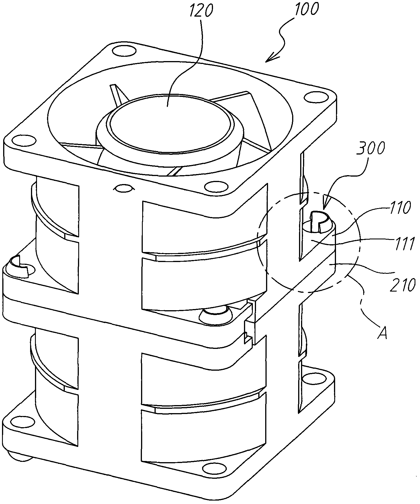
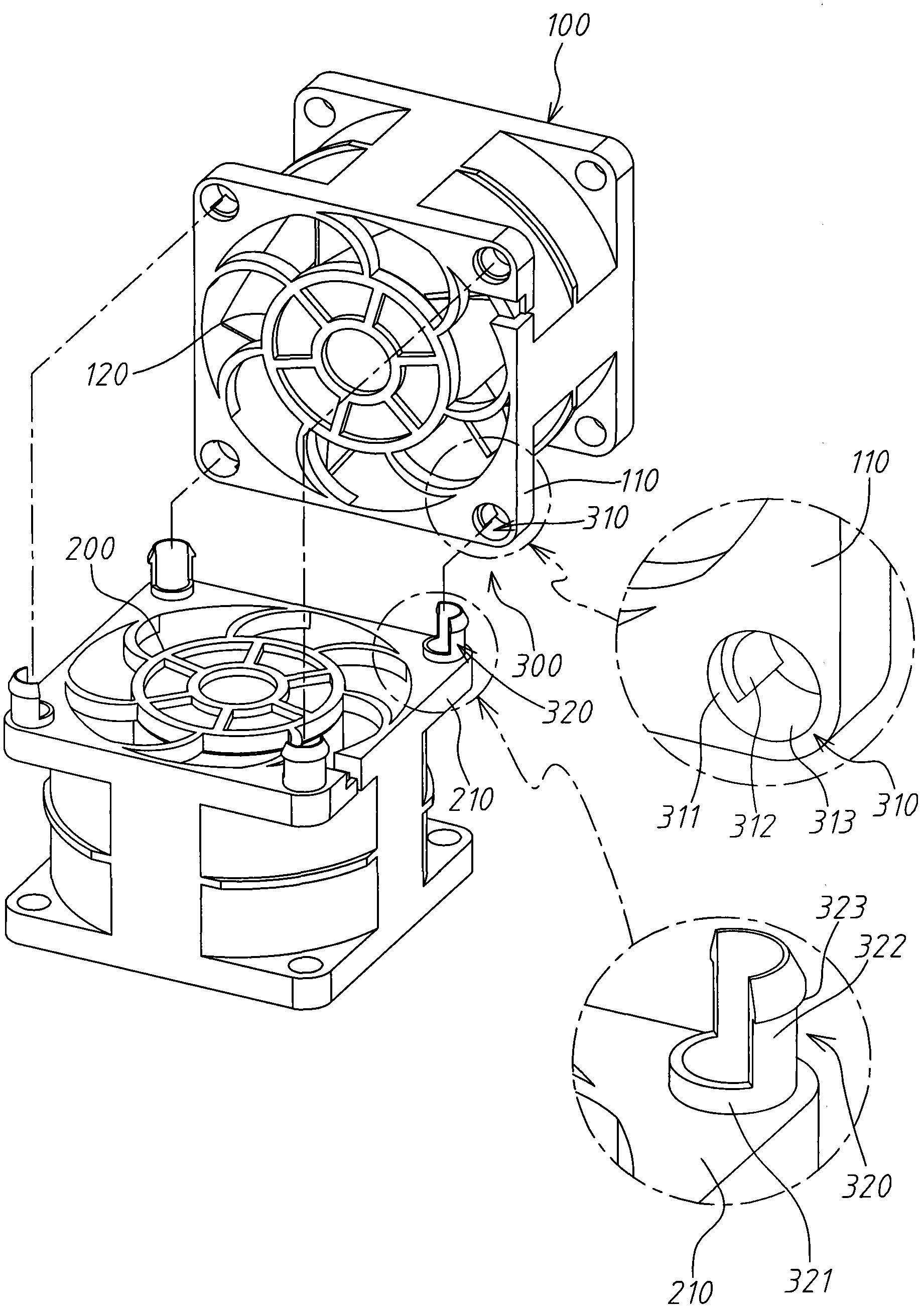
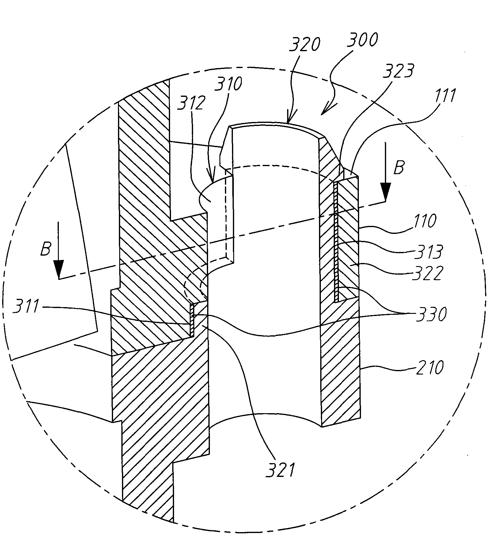
[0028] see Figure 1 to Figure 4 , which respectively show an appearance view, an exploded view, a longitudinal sectional view, and a transverse sectional view of the combined structure of the integrated fan according to an embodiment of the present invention. As shown in the figure, the combination structure of the integrated fan according to an embodiment of the present invention is used to combine two fans as a first fan 100 and a second fan 200. The combination structure 300 includes four combination holes 310, and The four combining holes match the four combining posts 320 of corresponding configuration, and the adhesive layer 330 is glued between the combining holes and the combining posts.

[0029] The size of the first fan 100 is, for examp...


PUM


Abstract

The invention discloses a combined structure of a combination fan. The combined structure is used for enabling at least two fans to be combined into a whole. The combined structure comprises at least one combination hole, at least one combination column and a sticking layer. The at least one combination hole is arranged in a frame body of a first motor in a penetrating mode. The at least one combination column is arranged in a frame body of a second motor in a protruding mode, the structure of the combination column is matched with that of the combination hole, and the combination column is contained in the combination hole in a penetrating mode. The sticking layer is arranged between the outer wall of the combination column and the inner wall of the combination hole in a sticking mode. Thus, the two frame bodies of the fan are firmly combined together.

Description

technical field [0001] The present invention relates to a combination structure, in particular to a combination structure of a combined fan. Background technique [0002] The fan is mainly used to dissipate heat from a heat-generating object, for example, to dissipate heat from a server. [0003] The air volume of the fan depends on the size of the fan and the horsepower of the fan motor. However, it is difficult and costly to manufacture a large-scale fan directly; therefore, it is usually made into a plurality of smaller unit motors, and then the unit motors are combined to form an integrated fan of a predetermined size. . For example, if you want to make a fan with a size of 40*40*56 (unit mm) used in a server, you usually make two unit fans with a size of 40*40*28 first, and then combine the two unit motors to form a 40*40*56 an all-in-one fan. [0004] To combine two or more unit fans into an integrated fan, a combined structure must be used. A known combined struc...

Claims


Application Information

Patent Timeline
IPC IPC(8): F04D25/16F04D29/52
Inventor 王炳麟
Owner 王炳麟
Why Eureka
Try Eureka