Supercharge Your Innovation With Domain-Expert AI Agents!

Applicator ram having a ram adaptor

An adapter and applicator technology, applied in the direction of circuit/collector parts, electrical components, connections, etc., which can solve the limitation of crimp height adjustment dial placement, difficulty in supplying the end of the terminator punch, and small dial size. And other issues

Active Publication Date: 2013-06-26
TE CONNECTIVITY CORP
View PDF3 Cites 0 Cited by
  • Summary
  • Abstract
  • Description
  • Claims
  • Application Information

AI Technical Summary

Problems solved by technology

The channel has tight tolerances to maintain a rigid bond between the applicator punch and the terminator punch, so it can be difficult to feed the end of the terminator punch into the channel
Additionally, the spacing between the terminator and applicator can be limited and the placement of the crimp height adjustment dial can be limited
This dial tends to be small, making it difficult to see the dial and difficult to adjust it precisely

Method used


Image

  • Applicator ram having a ram adaptor
  • Applicator ram having a ram adaptor
  • Applicator ram having a ram adaptor

Examples


Embodiment Construction

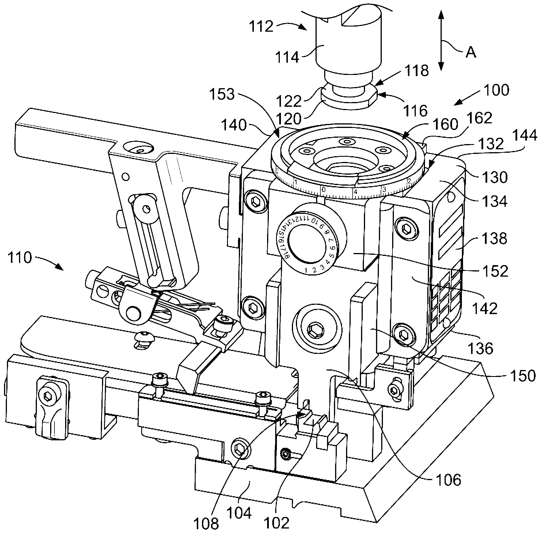
[0009] figure 1 is a front perspective view of an applicator 100 formed in accordance with an exemplary embodiment. The applicator 100 is used to crimp a terminal to the end of an electrical wire. The applicator 100 includes an anvil 102 secured in place on a base 104 supporting the applicator 100 . The applicator 100 includes a crimping tool 106 that is driven toward and away from the anvil 102 along a crimping stroke to crimp the terminal to the wire. A crimping region 108 is defined between the anvil 102 and the crimping tool 106 . The terminals are crimped to the wires within the crimp area 108 . In an exemplary embodiment, the applicator 100 includes a feeder 110 that feeds the terminals to the crimping area 108 during the crimping process.

[0010] In an exemplary embodiment, the applicator 100 is configured to be coupled to a terminator ram 112 of a terminator or termination machine (not shown). The terminator punch 112 is driven through the termination stroke by t...


PUM


Abstract

An applicator ram (150) includes a ram body (163) configured to hold crimp tooling, and a ram adaptor (160) coupled to the ram body (163). The ram adaptor is configured to be coupled to a terminator ram. The ram adaptor (160) includes an adaptor hub (170) having a hub chamber (200) configured to receive a ram post of the terminator ram. A latch mechanism (174) is movably received in the hub chamber (200). The latch mechanism (174) is movable between a latched position and an unlatched position. The latch mechanism (174) is configured to engage the ram post in the latched position. The latch mechanism (174) allows the ram post to be released from the hub chamber in the unlatched position. An adaptor stud (172) extends from the adaptor hub (170) and is configured to be coupled to the applicator ram.

Description

technical field [0001] The subject matter of this document generally relates to a wire termination machine. Termination machines are known for terminating terminals to wires, for example by a crimping process. A termination machine includes a motor that drives a terminator ram along a termination stroke. The terminator punch is connected to the applicator punch and drives the applicator punch along the crimping stroke. An applicator punch holds and drives the crimping tool along a crimping stroke to terminate the terminal to the wire. Background technique [0002] Known termination machines are not without disadvantages. For example, the connection between the applicator punch and the terminator punch can be difficult and time consuming to complete. Typically, the connection is what is known as a retaining hook type connection in which the end of the applicator punch has a hook or channel formed in the top. The end of the terminator punch fits sideways into the channel ...

Claims


Application Information

Patent Timeline
Patent Type & Authority Applications(China)
IPC IPC(8): H01R43/048
CPCH01R43/0488Y10T29/53235Y10T29/5327Y10T29/49185
Inventor B.K.韦弗K.J.斯特克姆
Owner TE CONNECTIVITY CORP
Features
  • R&D
  • Intellectual Property
  • Life Sciences
  • Materials
  • Tech Scout
  • Unparalleled Data Quality
  • Higher Quality Content
  • 60% Fewer Hallucinations
Learn More