Eureka AIR delivers breakthrough ideas for toughest innovation challenges, trusted by R&D personnel around the world.

Spark gap with a plurality of single spark gaps connected in series in a stacked arrangement

A technology of single spark gap and series connection, applied in the field of spark gap, can solve the problems of rising protection level, insufficient thermal coupling of protection devices, short circuit of separation gap, etc., and achieve the effect of residual voltage

Active Publication Date: 2014-10-08
デーンエスエープルスツェオーカーゲー
View PDF14 Cites 0 Cited by
  • Summary
  • Abstract
  • Description
  • Claims
  • Application Information

AI Technical Summary

Problems solved by technology

Because the material is plastically deformed under thermal influences, e.g. due to continuous flow of the flow and the constant pressure due to the screw connection of the laminated structure, and the individual separation gaps can thus be short-circuited
Such damage cannot be detected and indicated due to insufficient thermal coupling of the protective device that may be provided, resulting in tearing of the welded edge of the separation gap material when reloading, and no longer between the two electrodes. There are defined and as far as possible gap-free transitions and unintended rises of the protection level cannot be avoided

Method used


Image

  • Spark gap with a plurality of single spark gaps connected in series in a stacked arrangement
  • Spark gap with a plurality of single spark gaps connected in series in a stacked arrangement
  • Spark gap with a plurality of single spark gaps connected in series in a stacked arrangement

Examples


Embodiment Construction

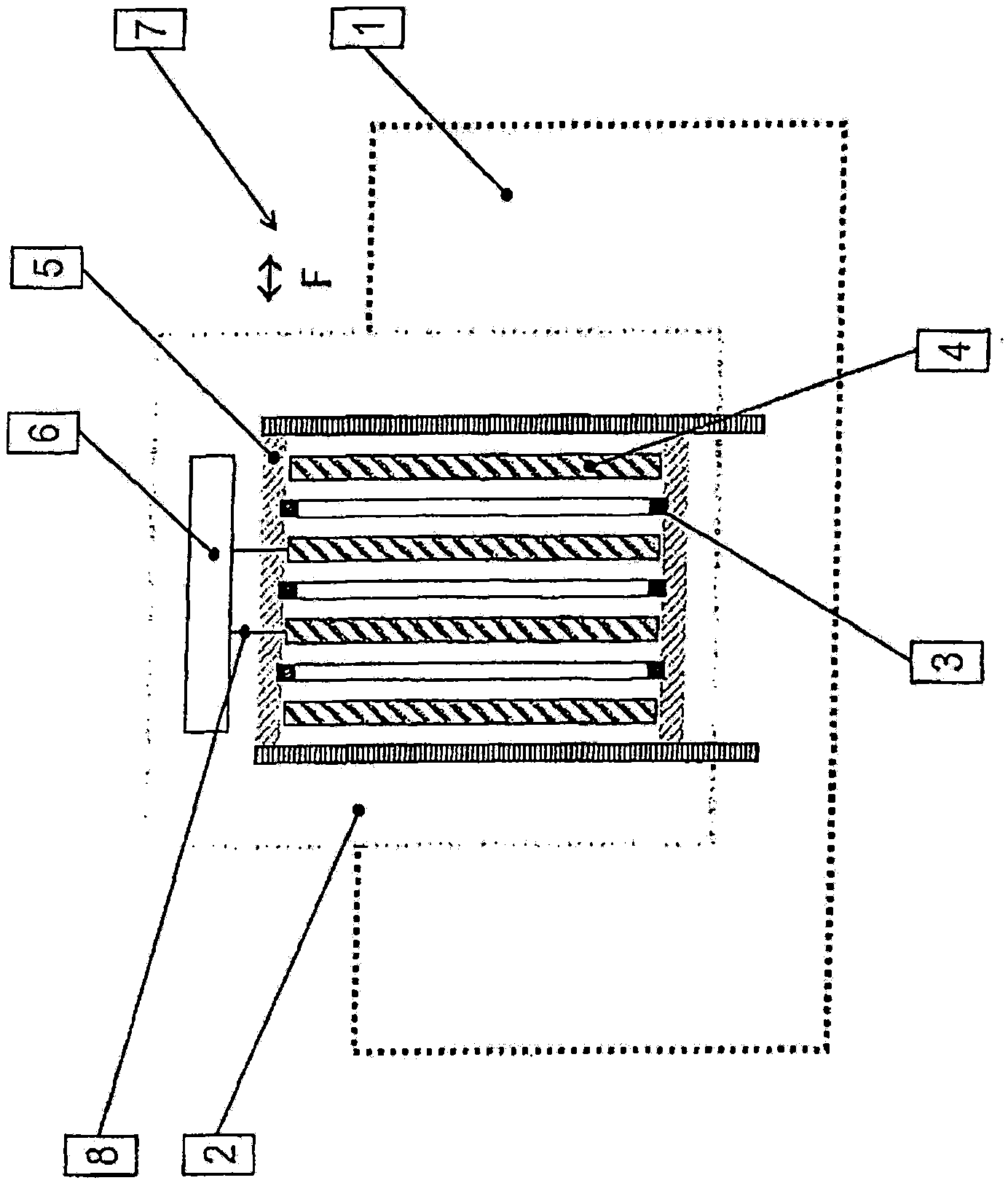
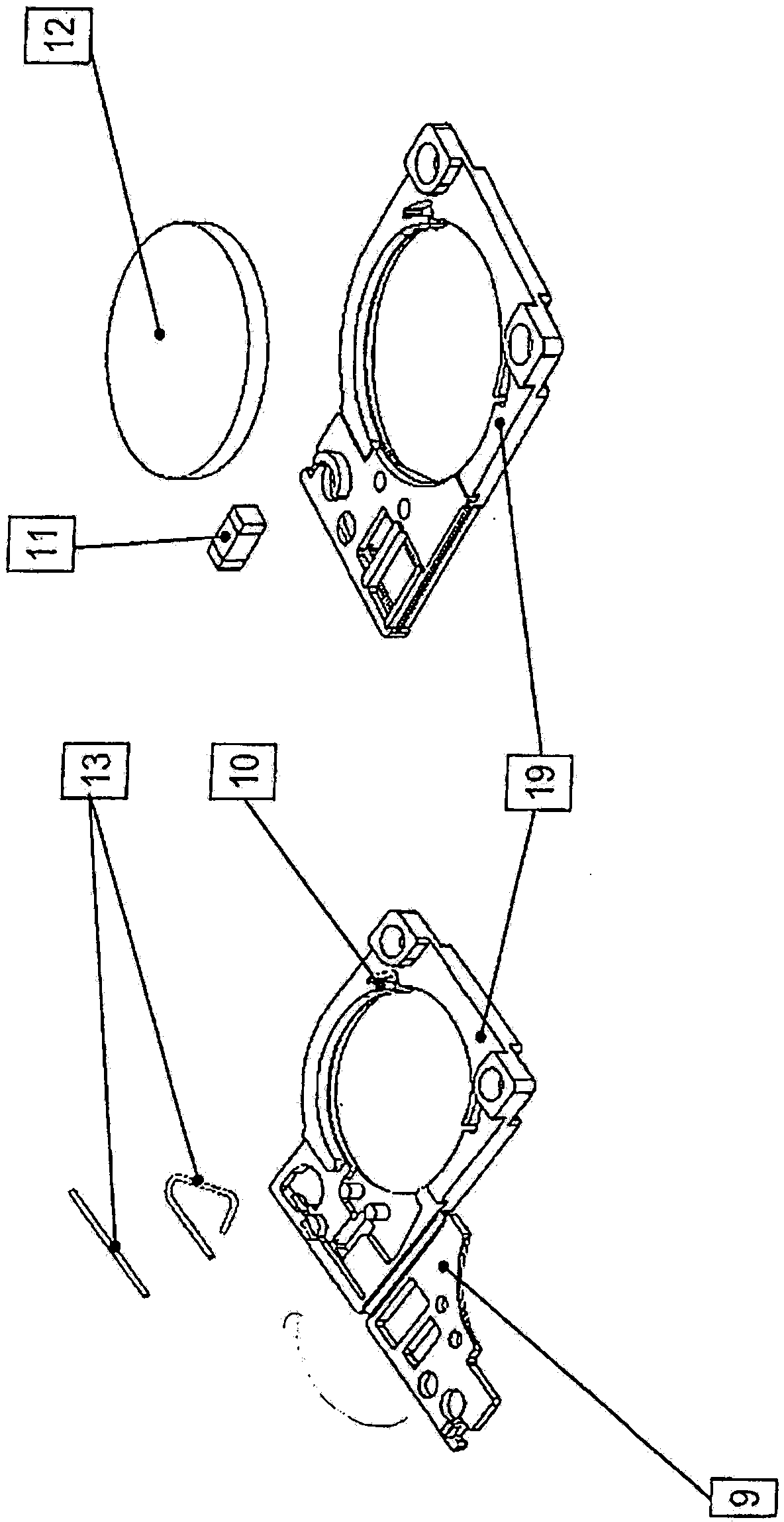
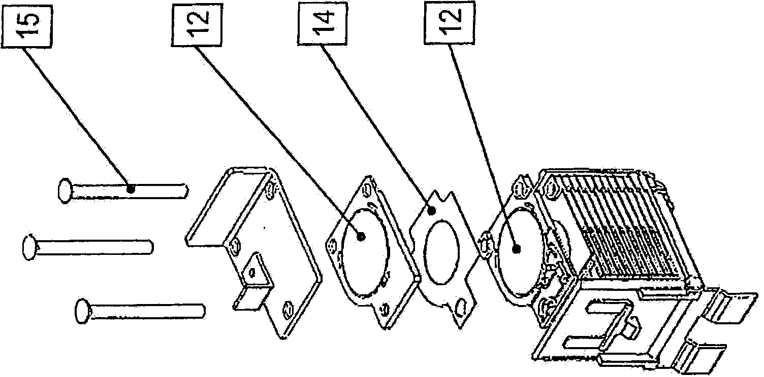
[0058] In order to eliminate the disadvantages of the prior art, an aging-resistant lightning current arrester is proposed according to the invention, which is implemented in a freewheeling manner and has a low response voltage and a residual voltage at the same time. The functional elements (such as graphite sheets), control elements and separation gaps of the individual spark gaps are designed as a single module and are separated from other loads such as pressure and soot and are therefore not compromised.

[0059] The embodiment without freewheeling is based on a series connection of the individual spark gaps with an additional control element. It is thus possible to obtain a spark arrester in which no freewheeling flow occurs, even in the presence of surge current loads, since the existing reverse voltage of the spark gap is always higher than the applied supply voltage.

[0060] A number of advantages are obtained by the freewheeling embodiment of the arrester according t...


PUM


Abstract

The invention relates to a spark gap comprising a number of series-connected individual spark gaps which are placed in a stack arrangement, which are spaced apart from each other by insulating material discs and are provided with a spring contact, the individual spark gaps including ring-shaped or disc-shaped electrodes, and further comprising control elements for influencing the voltage distribution over the stack arrangement. According to the invention the ring-shaped or disc-shaped electrodes required to form one of the respective individual spark gaps are each inserted into an insulating body and held by same in a centered manner. The respective insulating material discs are located between and fixed by the insulating bodies. A recess is provided inside the insulating body to receive and center the electrodes, whose shape is complementary relative to the contour of the respective electrode, wherein the recess comprises on the inner circumference at least partially elastic, resilient centering projections or centering noses.

Description

technical field [0001] The invention relates to a spark gap with a plurality of single spark gaps connected in series in a stacked arrangement, separated from each other by sheets of insulating material and provided with spring contact leads, said single spark gaps With electrodes in the form of rings or plates, the spark gap also has control elements to influence the voltage distribution on the stack. Background technique [0002] In known direct current applications, the arc current must be forced to zero by raising the voltage required for the arc to a value greater than the available supply voltage (principle of direct current extinction). According to the known arc equation, different starting points can be derived to raise the voltage of the arc involved, according to which the total arc voltage is obtained by summing the anode / cathode voltage drop and by the product of arc length and arc field strength . [0003] A particularly effective solution is to connect a plu...

Claims


Application Information

Patent Timeline
Patent Type & Authority Patents(China)
IPC IPC(8): H01T4/16
CPCH01T4/16
Inventor B·克劳斯M·瓦夫勒A·埃尔哈特S·施莱特S·拜尔
Owner デーンエスエープルスツェオーカーゲー
Why Eureka
Eureka Blog
Learn More