System used for determining three dimensional position of launching device relative to detecting device

A technology of three-dimensional position and emission device, which is applied in the direction of input/output process of optical device, measurement device, and data processing, etc., can solve the problems of insufficient control accuracy, high configuration cost, and high energy consumption, so as to improve control efficiency and reduce Configure cost and energy consumption level, improve the effect of control experience

Inactive Publication Date: 2013-07-10
XIAN ZIENON ELECTRONICS TECH
View PDF3 Cites 11 Cited by
  • Summary
  • Abstract
  • Description
  • Claims
  • Application Information

AI Technical Summary

Problems solved by technology

[0003] However, in the prior art, either only the two-dimensional position can be determined, or a more complex emission device or detection device is required, such as an emission device including multiple emission sources or a detection device including multiple detection points, to realize the determination 3D position
The former often has shortcomings such as insufficient control accuracy due to insufficient location information dimensions; while the latter supports control based on three-dimensional location information, but has disadvantages such as high configuration costs and high energy consumption.

Method used


Image

  • System used for determining three dimensional position of launching device relative to detecting device
  • System used for determining three dimensional position of launching device relative to detecting device
  • System used for determining three dimensional position of launching device relative to detecting device

Examples


Embodiment Construction

[0057] The present invention will be described in further detail below in conjunction with the accompanying drawings.

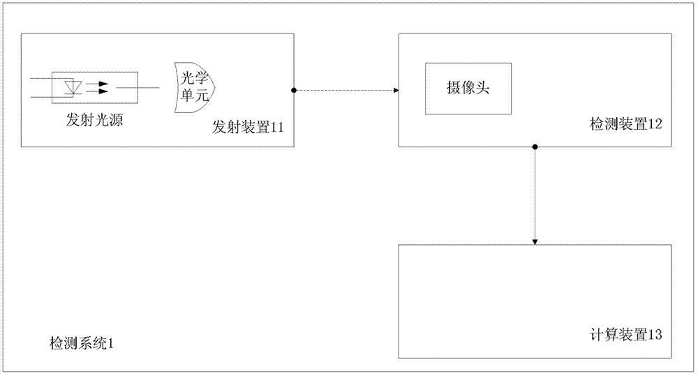
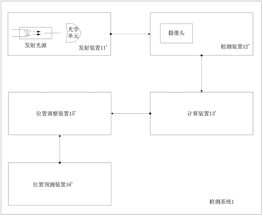
[0058] figure 1A schematic diagram of a system for determining the three-dimensional position of the emitting device relative to the detecting device is shown, wherein the detecting system 1 includes a emitting device 11 , a detecting device 12 and a computing device 13 .

[0059] The transmitting device 11 includes a transmitting light source for transmitting control signals, and an optical unit for assisting the transmission of the control signals. For example, in the emitting device 11, the emitting light source is located at the rear end of the optical unit, and the control signal emitted by the emitting light source is transmitted through the optical unit for the detection device 12 to obtain imaging information of the control signal through a camera therein. Or, the optical unit is located at the rear end of the emitting light source, and the optical u...


PUM


Abstract

The invention aims at providing a system used for determining the three dimensional position of a launching device relative to a detecting device. The system comprises the launching device, the detecting device and a calculating device, wherein the launching device comprises a launching light source used for sending a controlling signal and an optical unit used for assisting transmission of the controlling signal, the detecting device comprises a camera used for obtaining imaging information of the controlling signal through the optical unit in the camera, and the calculating device is used for determining the three dimensional position information of the launching device relative to the detecting device according to the imaging information. Compared with the prior art, the system for determining the three dimensional position of the launching device relative to the detecting device achieves determining of the three dimensional position of the launching device relative to the detecting device due to the fact that the launching device comprises the optical unit used for assisting the transmission of the controlling signal, not only lowers configuration cost and energy consumption level, but also enables controlling based on the three dimensional position information to be feasible, improves controlling efficiency, and enhances controlling experience of users.

Description

technical field [0001] The present invention relates to the technical field of intelligent control, in particular to a technology for determining the three-dimensional position of a transmitting device relative to a detecting device. Background technique [0002] In the field of intelligent control such as smart TV, somatosensory interaction, virtual reality, etc., the detection device usually detects a certain signal emitted by the emission device, such as the light signal sent by LED (Light Emitting Diode, light emitting diode), to perform corresponding control operations , such as turning the controlled device on or off. Among them, position information, especially the position information of the transmitting device relative to the detecting device, is of great significance for providing control accuracy and simplifying control operations. The interaction ability of the controlled device and improve the user's control experience. [0003] However, in the prior art, eith...

Claims


Application Information

Patent Timeline
Patent Type & Authority Applications(China)
IPC IPC(8): G01B11/00
CPCG01B11/002G06F3/0425G06F3/0304G06F3/005
Inventor 李东舸王玮魏院辉
Owner XIAN ZIENON ELECTRONICS TECH
Why Eureka
Try Eureka