Subarray time reversal mirror detection method

A technology of time inversion and detection method, applied in the field of multi-target detection, can solve the problem of inability to obtain target images, and achieve the effect of multi-target detection

Inactive Publication Date: 2014-11-05
UNIV OF ELECTRONICS SCI & TECH OF CHINA
View PDF2 Cites 0 Cited by
  • Summary
  • Abstract
  • Description
  • Claims
  • Application Information

AI Technical Summary

Problems solved by technology

[0056] The purpose of the present invention is to solve the problem that the traditional time inversion mirror method cannot obtain the correct target image when detecting multiple targets, and propose a sub-array time inversion mirror detection method

Method used


Image

  • Subarray time reversal mirror detection method
  • Subarray time reversal mirror detection method
  • Subarray time reversal mirror detection method

Examples


Embodiment Construction

[0067] Embodiments of the present invention will be further described below in conjunction with the accompanying drawings.

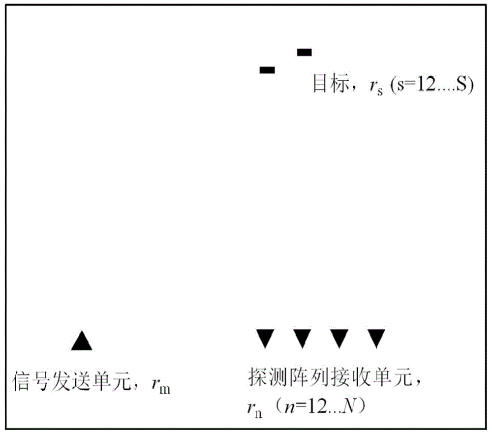
[0068] When designing a new time-reversal multi-target detection method, it is always hoped to use the time-reversal time-domain focusing property. Therefore, it is first necessary to obtain the time-domain physical properties of the time-reversal signals at multiple different targets, and then a new detection method can be constructed based on these physical properties. Before deriving these physical properties, first establish the attached figure 1 Probe model shown.

[0069] Assume that there are S scattering targets in the space, respectively located at r s (1≤s≤S). For simplicity of derivation, here it is assumed that the signal sending array consists of only one signal sending unit, and it is located at r m ; and ignoring the time-domain nonlinear characteristics of the array unit, the transfer function between the array signal sending unit and...


PUM


Abstract

The invention discloses a subarray time reversal mirror detection method which belongs to the technical field of time reversal, and aims at solving the problem that a correct target image cannot be obtained by a traditional time reversal mirror method when a plurality of targets are detected. According to the method disclosed by the invention, a time reversal detection array unit is divided into a plurality of subarrays, then data of each subarray is processed independently, and a target is found by looking for the common focus point of all the subarrays. Different from the traditional time reversal mirror detection method which utilizes signal intensity to mark a target position, the method disclosed by the invention utilizes signal focusing intensity to look for targets, thereby realizing detection on multiple targets.

Description

technical field [0001] The invention belongs to the technical field of time inversion, relates to the field of target detection, in particular to a multi-target detection method. Background technique [0002] Firstly, the mathematical description process of time reversal is introduced. Consider two sensors, defined as A and B, sending an excitation signal v(t) to sensor A, whose Fourier transform is V(ω). After passing through the sensor, the Fourier transform of the excitation signal obtained in space is P(ω). Since the sensor itself has nonlinear characteristics K a (ω) (if the sensor is an antenna, K a (ω) is the time-domain characteristic of the antenna; if the sensor is a piezoelectric sensor that excites the ultrasonic signal, then K a (ω) is the electromechanical conversion efficiency of the piezoelectric sensor), P(ω) can be expressed as: [0003] P(ω)=K a (ω)V(ω) (1-1) [0004] Let the nonlinear characteristic of sensor B be K b (ω), the time-domain output e...

Claims


Application Information

Patent Timeline
Patent Type & Authority Patents(China)
IPC IPC(8): G01S13/89G01S17/89
Inventor 洪劲松张光旻汪俊峰钟垒王秉中
Owner UNIV OF ELECTRONICS SCI & TECH OF CHINA
Why Eureka
Try Eureka