Unmanned aerial vehicle detection system and method based on digital array

A digital array and detection system technology, applied in the field of unmanned aerial vehicles, can solve the problems that multiple targets cannot be detected at the same time, and the target cannot be detected in real time.

Inactive Publication Date: 2017-05-17
上海资誉电子科技有限公司
View PDF5 Cites 0 Cited by
  • Summary
  • Abstract
  • Description
  • Claims
  • Application Information

AI Technical Summary

Problems solved by technology

The infrared camera controlled by the turntable cannot detect multiple targets at the same time in a complex environment, and cannot detect the target in real time

Method used


Image

  • Unmanned aerial vehicle detection system and method based on digital array
  • Unmanned aerial vehicle detection system and method based on digital array
  • Unmanned aerial vehicle detection system and method based on digital array

Examples


Embodiment 1

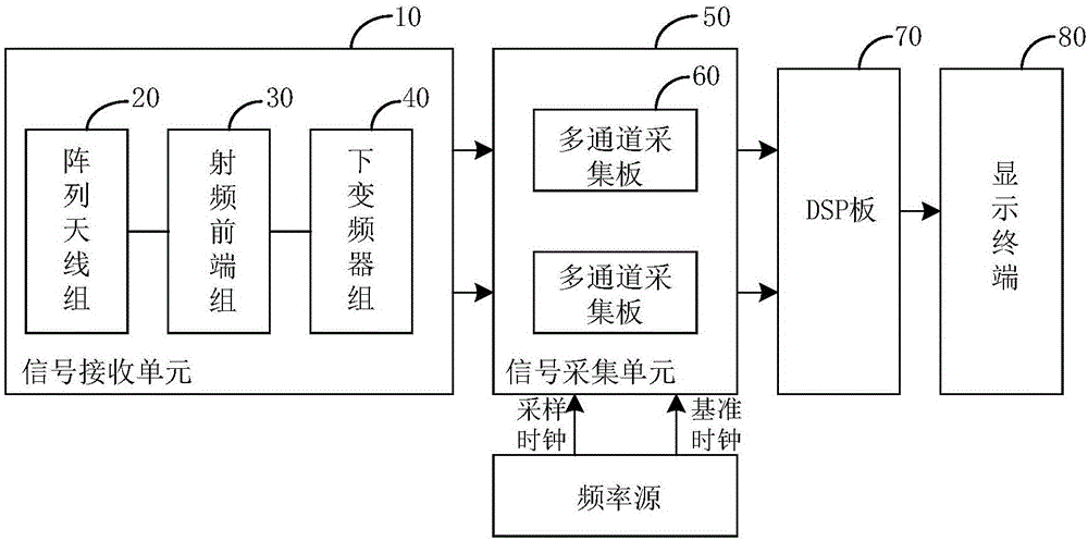
[0053] figure 1 A schematic diagram of a digital array-based UAV detection system provided by an embodiment of the present invention.

[0054] refer to figure 1 , the system includes a signal receiving unit 10, a signal acquisition unit 50, a digital signal processing DSP board 70 and a display terminal 80;

[0055] The signal receiving unit 10 is connected to the signal acquisition unit 50, and is used to receive the image transmission analog signal sent by the UAV, filter and amplify the image transmission analog signal, and obtain an amplification whose passband is the first frequency range The video transmission analog signal, converting the amplified video transmission analog signal whose passband is the first frequency range into the amplified video transmission analog signal whose passband is the second frequency range;

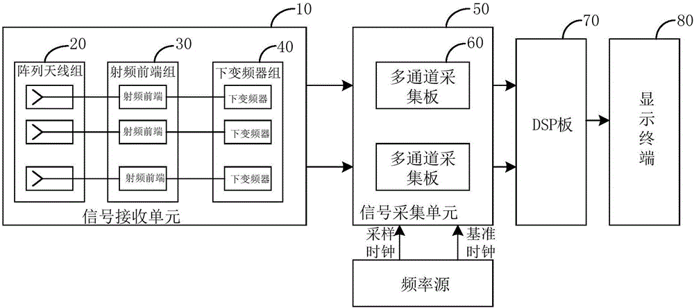
[0056] Specifically, the signal receiving unit 10 includes an array antenna group 20, a radio frequency front end group 30 and a down converter grou...

Embodiment 2

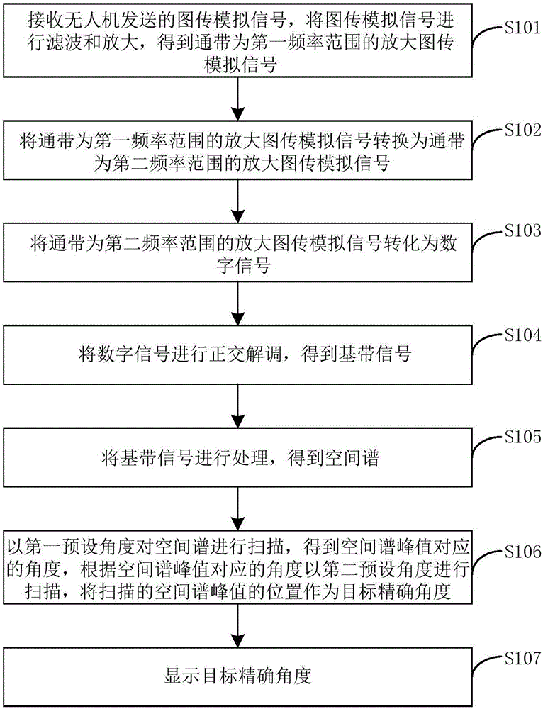
[0081] image 3 It is a flow chart of the digital array-based UAV detection method provided by the embodiment of the present invention.

[0082] refer to image 3 , the method includes the following steps:

[0083] Step S101, receiving the video transmission analog signal sent by the UAV, filtering and amplifying the video transmission analog signal, and obtaining the amplified video transmission analog signal with the passband in the first frequency range;

[0084] Step S102, converting the amplified video transmission analog signal whose passband is in the first frequency range into an amplified video transmission analog signal whose passband is in the second frequency range;

[0085] Step S103, converting the amplified video transmission analog signal whose passband is the second frequency range into a digital signal;

[0086] Step S104, performing quadrature demodulation on the digital signal to obtain a baseband signal;

[0087] Step S105, processing the baseband sign...


PUM


Abstract

The invention provides an unmanned aerial vehicle detection system and method based on digital arrays. The method includes the following steps: receiving an image transmission analog signal sent from an unmanned aerial vehicle, filtering and amplifying the image transmission analog signal, and obtaining an amplified image transmission analog signal with a passband being in the first frequency range; converting the amplified image transmission analog signal with the passband being in the first frequency range into an amplified image transmission analog signal with a passband being in the second frequency range; converting the amplified image transmission analog signal with the passband being in the second frequency range into a digital signal; conducting quadrature demodulation on the digital signal, and obtaining a baseband signal; processing the baseband signal, and obtaining a space spectrum; scanning the space spectrum at a first preset angle, obtaining an angle corresponding to a peak value of the space spectrum, scanning at a second preset angle according to the angle corresponding to the peak value of the space spectrum, and taking the scanned position of the peak value of the space spectrum as a target accurate angle; and displaying the target accurate angle. Therefore, real-time detection of a target can be carried out, and detection of multiple targets can be realized in a complex environment.

Description

technical field [0001] The invention relates to the technical field of unmanned aerial vehicles, in particular to an unmanned aerial vehicle detection system and method based on a digital array. Background technique [0002] With the rapid development of UAVs, UAVs have been widely used in fields such as video acquisition, geological exploration, remote sensing mapping, and search and rescue. Therefore, the detection and early warning technology and equipment of UAVs have become the hotspots of current research. [0003] At present, UAV detection equipment collects image data through infrared thermal imaging cameras, and transmits image data to image processors for processing, thereby completing target detection. Usually, the search area of ​​the infrared camera is controlled by the turntable, and the beam pointing is controlled by the turntable, and only one target can be detected at the same time. The infrared camera controlled by the turntable cannot detect multiple tar...

Claims


Application Information

Patent Timeline
Patent Type & Authority Applications(China)
IPC IPC(8): G01V3/17
CPCG01V3/17
Inventor 李卫星李海锋帅博邹世民吴波张建森来飞汪建黄文辉
Owner 上海资誉电子科技有限公司
Why Eureka
Try Eureka