
LED (Light-Emitting Diode) daylight lamp

A technology for heat dissipation of LED fluorescent lamps and aluminum, applied in the direction of light source, electric light source, light source fixing, etc., can solve the problems of cumbersome operation, affecting lighting effect, and inability to adjust the lamp tube, and achieve the effect of convenient installation or maintenance

Inactive Publication Date: 2015-05-27
SHENZHEN TOP TECH
View PDF4 Cites 0 Cited by
  • Summary
  • Abstract
  • Description
  • Claims
  • Application Information

AI Technical Summary

Problems solved by technology

Since the LED fluorescent lamp of the prior art can only emit light in one direction, it is necessary to direct the side of the circuit board with the LED light-emitting element to the direction to be illuminated during installation, but sometimes the positions of the socket holes are different. The prior art The lamp tube cannot be adjusted, causing the side of the LED light-emitting element of the circuit board to sometimes not just face the direction to be irradiated, which affects the lighting effect
Moreover, when installing or maintaining fluorescent lamps in the prior art, it is necessary to use special tools such as screwdrivers to disassemble the LED light bar and transparent parts, and the operation is relatively cumbersome.

Method used


Image

  • LED (Light-Emitting Diode) daylight lamp
  • LED (Light-Emitting Diode) daylight lamp
  • LED (Light-Emitting Diode) daylight lamp

Examples


Embodiment Construction

[0030] In order to facilitate the understanding of the present invention, the present invention will be described more fully below with reference to the associated drawings. Preferred embodiments of the invention are shown in the accompanying drawings. However, the present invention can be embodied in many different forms and is not limited to the embodiments described herein. On the contrary, these embodiments are provided to make the understanding of the disclosure of the present invention more thorough and comprehensive.

[0031] It should be noted that when an element is referred to as being “fixed” to another element, it can be directly on the other element or there can also be an intervening element. When an element is referred to as being "connected to" another element, it can be directly connected to the other element or intervening elements may also be present. The terms "vertical," "horizontal," "left," "right," and similar expressions are used herein for purposes ...


PUM


Abstract

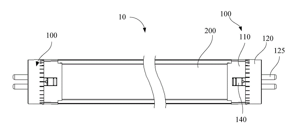
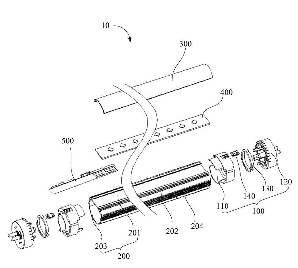
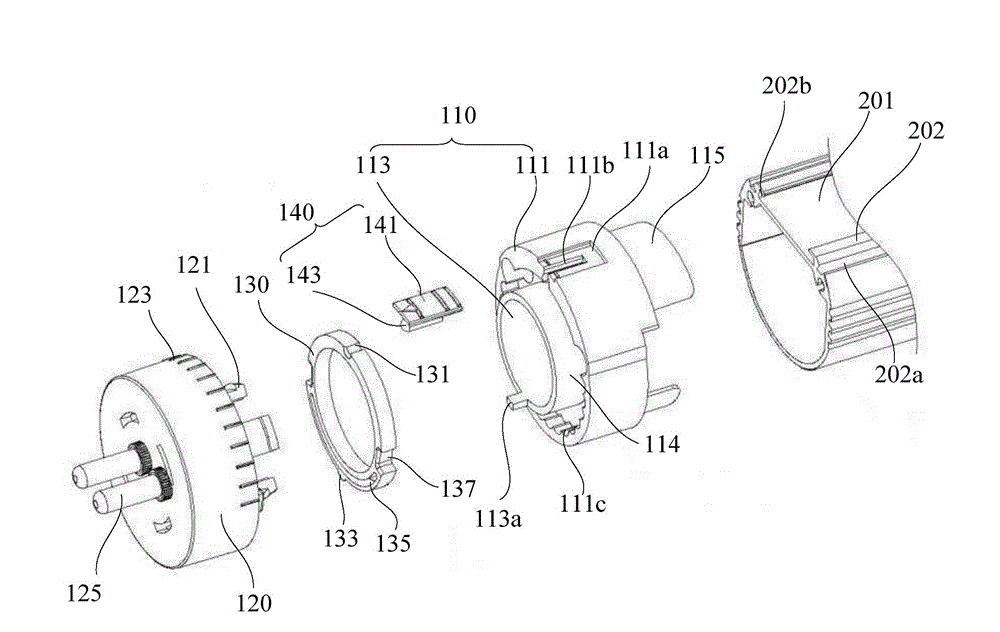
The invention provides an LED (Light-Emitting Diode) daylight lamp comprising two lamp holder structures, an aluminum heat dissipation shell, a transparent piece and LED lamp strips, wherein each lamp holder structure comprises a front end cover, a rear end cover, a rotating shaft and a spacing piece; the front end cover comprises an outer barrel and an inner barrel which are arranged at an interval, and an annular accommodating groove is formed between the inner barrel and the outer barrel; the outer wall of the outer barrel is provided with a sliding chute and a slot; the slot penetrates through the bottom of the sliding chute and is communicated with the accommodating groove; the inner wall of the outer barrel is provided with a matching part; the rear end cover is detachably connected with the front end cover, and the front end cover can rotate relative to the rear end cover; the rotating shaft is arranged in the rear end cover and fixedly connected with the rear end cover; the rotating shaft is of an annular structure; the outer periphery of the rotating shaft is provided with a spacing slot and a positioning part; the positioning part is matched with the matching part, so as to position the front end cover to a position with a preset angle; the spacing piece comprises a base plate and a spacing boss arranged on the bottom surface of the base plate; and the spacing boss passes through the slot and props against the interior of the spacing slot. The LED daylight lamp is rotatable and adjustable, can perform angle positioning, and is more convenient in installation and maintenance.

Description

【Technical field】 [0001] The invention relates to an LED fluorescent lamp, in particular to a lamp cap structure of an LED fluorescent lamp with a rotatable lamp cap. 【Background technique】 [0002] LED technology is widely used. When LED is used as a fluorescent lamp, it consumes less power and has soft light. Its main structure is: a circuit board installed in the fluorescent tube, LED light-emitting elements are installed on the circuit board, and then through the power line on the circuit board Connect the junction point on the lamp head, the junction point is connected to the binding post at the end of the lamp head, the binding post is inserted into the socket hole, and the fluorescent lamp will emit light after being powered on. Since the LED fluorescent lamp of the prior art can only emit light in one direction, it is necessary to direct the side of the circuit board with the LED light-emitting element to the direction to be illuminated during installation, but somet...

Claims


Application Information

Patent Timeline
Patent Type & Authority Patents(China)
IPC IPC(8): F21S2/00F21V19/02F21V17/10F21Y101/02F21K9/27F21K9/275F21Y115/10
Inventor 唐义国楚阿真庞桂伟庞桂兑
Owner SHENZHEN TOP TECH
Learn More