
Synchronizer structure capable of preventing secondary impact during gear shift

A secondary impact and synchronizer technology, applied in the direction of clutches, mechanical drive clutches, mechanical equipment, etc., can solve the problems of secondary impact, obstruction, driver's uncomfortable hand shifting, etc., so as to avoid secondary impact and prevent secondary impact. Second impact, well-structured effect

Active Publication Date: 2013-08-07
ZHEJIANG WANGLIYANG TRANMISSION CO LTD
View PDF7 Cites 7 Cited by
  • Summary
  • Abstract
  • Description
  • Claims
  • Application Information

AI Technical Summary

Problems solved by technology

At present, most of the synchronizers used in transmissions are inertial lock ring synchronizers. Although there are many types of structures, the basic working principle is the same, that is, to synchronize the two meshing rotating parts to make them rotate at the same speed. At the same time, it is necessary to ensure that the moment of inertia generated by the friction pair is used to prevent their out-of-synchronous meshing and achieve locking before they are not synchronized. The meshing teeth mesh to complete the shifting process, and due to structural reasons, the lock ring synchronizers currently used have the following disadvantages: after the two moving parts to be meshed are synchronized, the lock is released, and the gear sleeve continues to move forward and align with the gear sleeve. During the meshing process of the gear teeth, there will inevitably be obstacles, forming a secondary impact, causing the driver to feel uncomfortable when shifting gears

Method used


Image

  • Synchronizer structure capable of preventing secondary impact during gear shift
  • Synchronizer structure capable of preventing secondary impact during gear shift
  • Synchronizer structure capable of preventing secondary impact during gear shift

Examples


Embodiment Construction

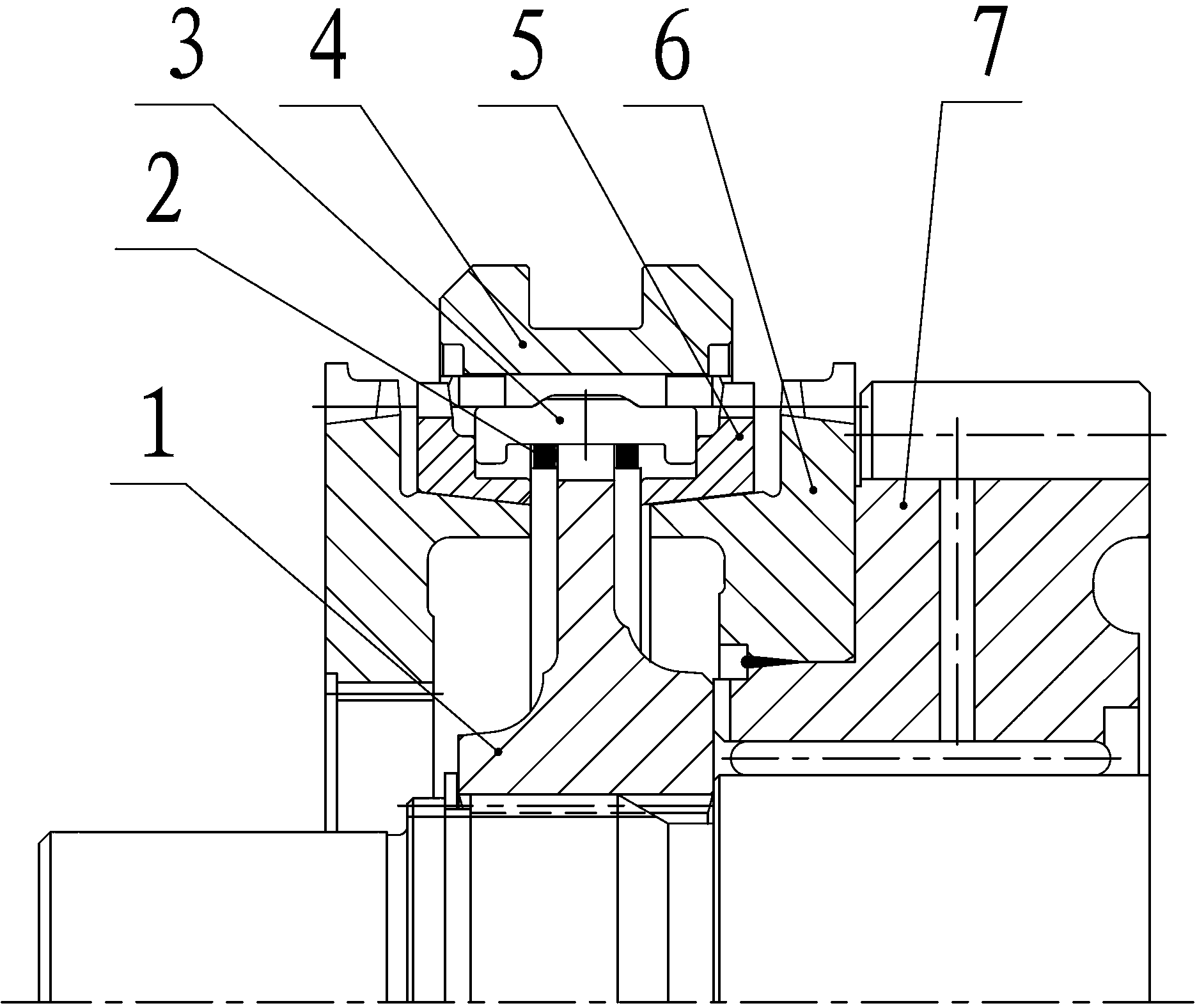
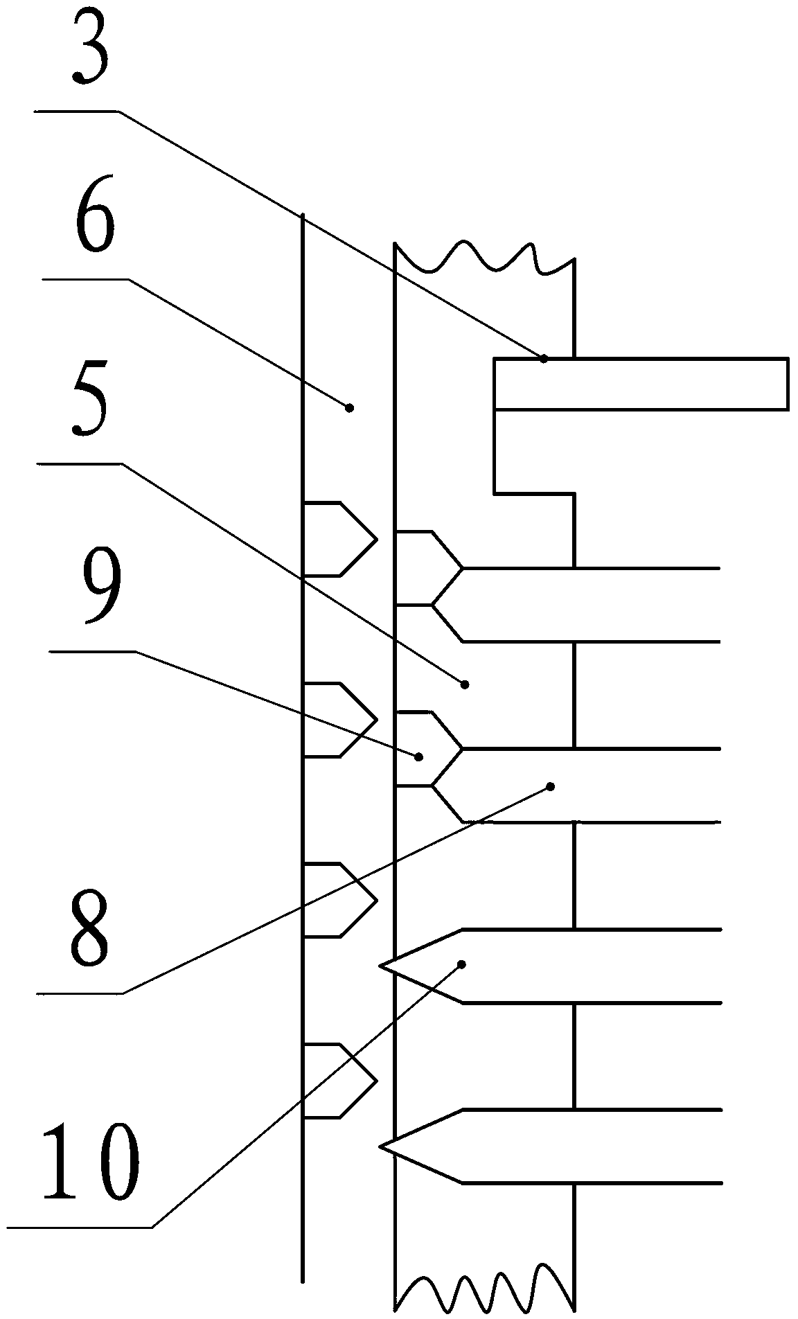
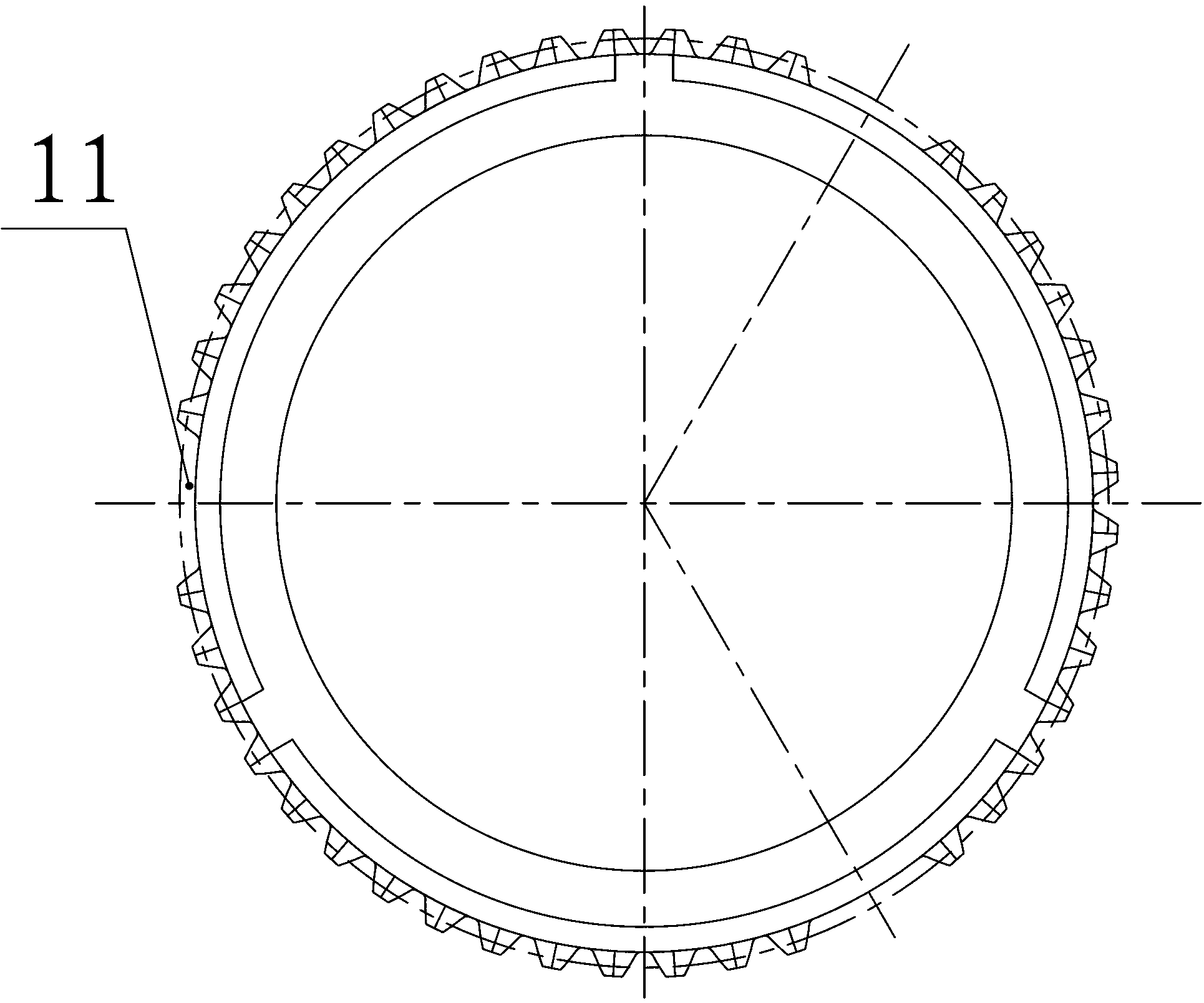
[0010] like figure 1 As shown, the synchronizer structure for preventing the secondary impact of gear shifting is mainly composed of tooth seat 1, spring 2, slider 3, tooth sleeve 4, synchronous ring 5, engaging teeth 6, and gear 7. The tooth seat 1 passes through The inner spline is fixedly connected to the transmission shaft, the gear sleeve 4 is installed on the gear base 1 and can slide freely left and right on the gear base 1, the slider 3 is installed between the gear base 1 and the gear sleeve 4, and the gear sleeve 4 can drive it Axially moving, the engaging tooth 6 rotates with the gear 7. It is characterized in that: the gear sleeve 4 has a locking tooth 8, and the locking tooth 8 contacts and locks with the corresponding synchronous ring locking tooth 9, and the gear sleeve 4 There is also a aligning tooth 10, the angle of inversion of the aligning tooth 10 is smaller than that of the locking tooth 8, and the axial dimension is slender, and there is a gap in the cor...


PUM


Abstract

The invention belongs to automotive transmissions and particularly relates to a synchronizer structure capable of preventing a secondary impact during gear shift. The synchronizer structure is composed of a tooth holder, a synchronizing ring, a spring, a sliding block, a tooth sleeve, joint teeth and a gear, wherein the tooth holder is fixedly connected onto a transmission shaft through an internal spline, the tooth sleeve is installed on the tooth holder and capable of freely sliding on the tooth holder left and right, the sliding block is arranged between the tooth holder and the tooth sleeve and capable of moving axially under the drive of the tooth sleeve, and the joint teeth rotate along with the gear. The synchronizer structure is characterized in that the tooth sleeve is provided with a locking tooth, the locking tooth contacts with a corresponding synchronizing ring locking tooth and is locked, the tooth sleeve is further provided with an alignment tooth, the chamfered angle of the alignment is smaller than that of the locking tooth, the axial dimension is long and thin, and a notch is arranged at a position corresponding to the synchronizing ring. According to the synchronizer structure, the structure is reasonable, the gear shift is stable, a driver feels comfortable during gear shift, and the secondary impact during gear shift is prevented effectively.

Description

technical field [0001] The invention belongs to the category of automobile transmissions, in particular to a synchronizer structure for preventing secondary impact of shifting. Background technique [0002] Synchronizers are commonly used during gear shifting in mechanical gear transmissions. At present, most of the synchronizers used in transmissions are inertial lock ring synchronizers. Although there are many types of structures, the basic working principle is the same, that is, to synchronize the two meshing rotating parts to make them rotate at the same speed. At the same time, it is necessary to ensure that the moment of inertia generated by the friction pair is used to prevent their out-of-synchronous meshing and achieve locking before they are not synchronized. The meshing teeth mesh to complete the shifting process, and due to structural reasons, the lock ring synchronizers currently used have the following disadvantages: after the two moving parts to be meshed are...

Claims


Application Information

Patent Timeline
IPC IPC(8): F16D23/02
Inventor 申文权陆晓平李小兰乔湘鹤沈黄桥蒙远春
Owner ZHEJIANG WANGLIYANG TRANMISSION CO LTD
Learn More