Coating impact fatigue test device

A technology of impact fatigue and experimental equipment, applied in the direction of measuring equipment, instruments, scientific instruments, etc., can solve the problems of inconvenient operation, difficulty in achieving high-energy impact, and difficulty in impacting to the same position, so as to avoid secondary impact, Ease of use and simple structure

Active Publication Date: 2018-03-30
WUXI FULAIDA PETROLEUM MACHINERY
View PDF8 Cites 6 Cited by
  • Summary
  • Abstract
  • Description
  • Claims
  • Application Information

AI Technical Summary

Problems solved by technology

To realize the impact of different energies, it is necessary to change the falling height of the steel ball, and the corresponding height of the workbench and the length of the conduit must be replaced, which is inconvenient to operate
Due to the limitation of the height of the experimental device, it is difficult to achieve a large energy impact
In addition, since the inner diameter of the guide tube of the falling ball is larger than the diameter of the steel ball used, when the steel ball flies out of the guide tube and hits the coating sample, it is difficult to hit the same position, thus affecting the impact fatigue resistance of the coating. evaluation of

Method used


Image

  • Coating impact fatigue test device
  • Coating impact fatigue test device
  • Coating impact fatigue test device

Examples


Embodiment Construction

[0024] The present invention will be further described below in conjunction with specific drawings.

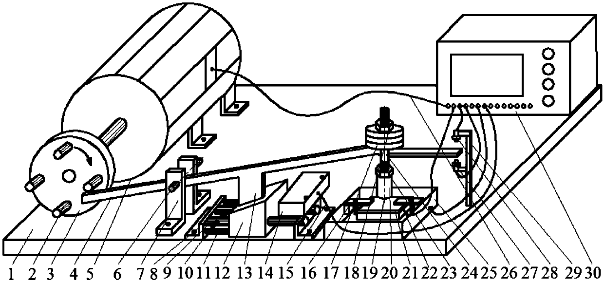
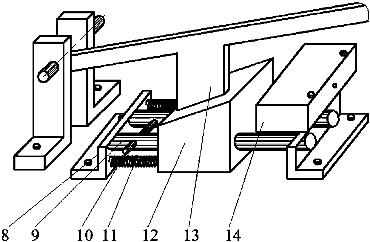
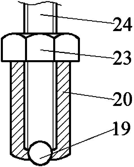
[0025] Such as Figure 1-Figure 3 As shown, the coating impact fatigue test device of the present invention comprises a base 1, a rotating shaft support 7 is installed on the base 1, a rotating shaft 6 on the rotating shaft support 7 supports a lever 4, and a speed regulating motor 5 is installed on the base 1 at the left end of the lever 4, The power output shaft of the speed-regulating motor 5 is connected to the turntable 3, and four shift forks 2 are arranged on the turntable 3 along the circumferential direction. During the rotation of the turntable 3, the four shift forks 2 can sequentially press down the left end of the lever for a certain distance, and then connect with the lever. Disengaged, so that the right end of the lever rises and falls freely, thereby realizing the repeated impact of the hard alloy ball fixed under the right end of the lever on the coating sampl...


PUM


Abstract

The invention relates to a coating impact fatigue test device. The coating impact fatigue test device comprises a pedestal and is characterized in that a rotation driving device and a lever are arranged on the pedestal; an output shaft of the rotation driving device is connected with a rotating disk; a plurality of shifting forks are arranged on the rotating disk; a weight is arranged at the rightend of the lever; the lever on the lower part of the weight is connected with a screw rod and a sleeve nut; a hard alloy ball is arranged at the bottom of the sleeve nut; a coating sample block clampis arranged below the hard alloy ball; an upper wedge-shaped block is arranged on the middle part of the lever; the inclined surface of the lower end of the upper wedge-shaped block is matched with the inclined surface of the upper end of the lower wedge-shaped block; an electromagnet is arranged on the right side of the lower wedge-shaped block; the electromagnet attracts the lower wedge-shapedblock to move rightwards when being electrified; an upper infrared induction switch and a lower infrared induction switch are arranged on the pedestal of the right end of the lever; a guide rod is arranged on the pedestal; the guide rod is in sliding fit with the lower wedge-shaped block; and an elastic piece is connected between a guide rod bracket and the lower wedge-shaped block. The coating impact fatigue test device is simple in structure and convenient to use, and can realize impact fatigue performance test of the coating sample.

Description

technical field [0001] The invention relates to an experimental device of fatigue performance, in particular to a coating impact fatigue experimental device. Background technique [0002] Coated mechanical parts are often subjected to impacts of different energies in addition to common damage such as wear and corrosion during service. Long-term impact will cause fatigue cracking and peeling of the coating. When the coating is subjected to a combination of wear and (or) corrosion, the failure process of the coating will be further accelerated. Therefore, it is very necessary to carry out the evaluation of the impact fatigue resistance of the coating, especially the research on the impact failure process of the coating under the action of different temperatures or corrosive media. The patent "a falling ball test device capable of automatic temperature control" (201410776451.4) uses the falling ball impact method to test the impact fatigue resistance of the coating. The device...

Claims


Application Information

Patent Timeline
Patent Type & Authority Applications(China)
IPC IPC(8): G01N3/34
CPCG01N3/34G01N2203/0073
Inventor 章诗岐
Owner WUXI FULAIDA PETROLEUM MACHINERY
Why Eureka
Try Eureka