On-orbit frequency increasing mechanism for spacecraft flexible appendage

A technology for spacecraft and accessories, applied in the field of flexible accessory frequency increasing mechanisms, can solve the problems affecting the reliability and stability of key loads, the failure of satellite platforms in an ultra-statically indeterminate state, and the abnormal operation of satellite loads. Dynamically expand the effects of power consumption, light weight, and guaranteed reliability and applicability

Active Publication Date: 2013-08-14
SHANGHAI SATELLITE ENG INST
View PDF6 Cites 3 Cited by
  • Summary
  • Abstract
  • Description
  • Claims
  • Application Information

AI Technical Summary

Problems solved by technology

On the other hand, the movement of the active parts such as the reaction flywheel, servo mechanism, and gyroscope of the spacecraft in orbit becomes a source of dynamic disturbance, which is prone to coupling and resonance with flexible accessories, which will have a negative impact on the attitude of the entire star and may affect some key loads. Work reliability and stability
[0003] According to the above analysis, coupling resonance is a common phenomenon on spacecraft, and its occurrence will cause some structural parts to couple with some moving parts under unexpected circumstances, thus destroying the hyperstatic state of the satellite platform and lightly If it interferes with the attitude of the whole satellite, it will cause the satellite load to work abnormally.

Method used


Image

  • On-orbit frequency increasing mechanism for spacecraft flexible appendage
  • On-orbit frequency increasing mechanism for spacecraft flexible appendage

Examples


Embodiment Construction

[0026] The embodiments of the present invention are described in detail below: this embodiment is implemented under the premise of the technical solution of the present invention, and detailed implementation methods and specific operating procedures are provided. It should be noted that those skilled in the art can make several modifications and improvements without departing from the concept of the present invention, and these all belong to the protection scope of the present invention.

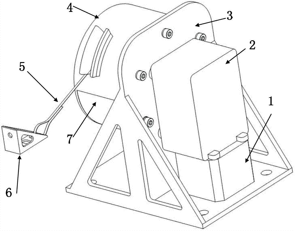
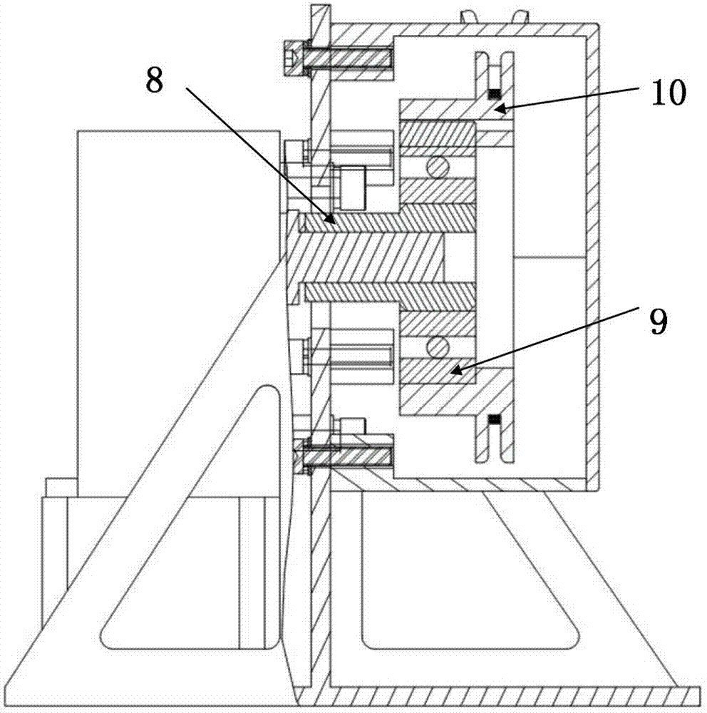
[0027] Such as figure 1 As shown, this embodiment provides an on-orbit frequency-increasing mechanism for a flexible accessory of a spacecraft, including a drive element, a deceleration device, a support frame, a stay rope webbing, an interface support, a transition shaft section, a one-way bearing and The bobbin, the driving element, the deceleration device, the interface support, the transition shaft section, the one-way bearing and the bobbin are respectively installed on the support fram...


PUM


Abstract

The invention discloses an on-orbit frequency increasing mechanism for a spacecraft flexible appendage. The on-orbit frequency increasing mechanism comprises a driving element, a speed reducing device, a support frame, a woven stay cord belt, a joint support, a transitional shaft section, a unidirectional bearing and a winding reel, wherein the driving element, the speed reducing device, the joint support, the transitional shaft section, the unidirectional bearing and the winding reel are respectively mounted on the support frame, the woven stay cord belt is wound on the winding reel, driving power of the driving element is transmitted to the winding reel via the speed reducing device, the transitional shaft section and the unidirectional bearing, the winding reel rotates to drive the woven stay cord belt to be tensioned and loosened, and an end portion of the woven stay cord belt is connected with the flexible appendage. By the on-orbit frequency increasing mechanism for the spacecraft flexible appendage, the problem that the spacecraft flexible appendage is too low in fundamental frequency or frequency is required to be improved for coupling of lower-order frequency and on-satellite disturbance source. Meanwhile, the on-orbit frequency increasing mechanism for the spacecraft flexible appendage has the advantages of light weight, simplicity in control, small size, capability of being unfolded along movement, low consumption and the like, and can effectively guarantee reliability and applicability of the spacecraft flexible appendage in the on-orbit frequency increasing mechanism.

Description

technical field [0001] The invention relates to a flexible accessory frequency increasing mechanism in the technical field of spacecraft, in particular to an on-orbit frequency increasing mechanism for a spacecraft flexible accessory. Background technique [0002] With the development of aerospace technology, modern spacecraft are developing in the direction of large-scale, low rigidity and flexibility. The fundamental frequency of the flexible appendage of the spacecraft is low, and the low-frequency dense phenomenon is also obvious. On the other hand, the movement of the active parts such as the reaction flywheel, servo mechanism, gyroscope, etc. of the spacecraft in orbit becomes the power disturbance source, and it is easy to generate coupling and resonance with the flexible accessories, which will have a negative impact on the attitude of the whole star and may affect some key loads. Work reliability and stability. [0003] According to the above analysis, coupling re...

Claims


Application Information

Patent Timeline
Patent Type & Authority Applications(China)
IPC IPC(8): B64G1/24
Inventor 薛景赛王萌王智磊杜三虎张涛张如变
Owner SHANGHAI SATELLITE ENG INST
Why Eureka
Try Eureka