Device for controlling electrical discharge machine
A technology of electric discharge processing machine and control device, which is applied in the direction of electric processing equipment, metal processing equipment, circuits, etc., and can solve the problem of prolonged stop time
- Summary
- Abstract
- Description
- Claims
- Application Information
AI Technical Summary
Problems solved by technology
Method used
Image
Examples
Embodiment approach 1
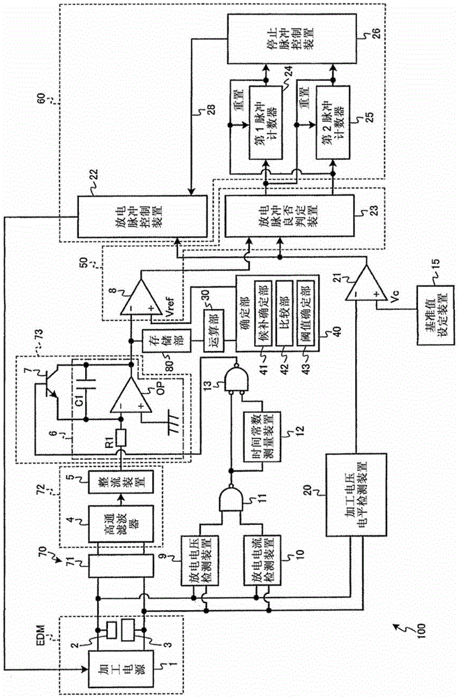
[0029] use figure 1 Next, the control device 100 for the electrical discharge machine EDM according to Embodiment 1 will be described. figure 1 It is a figure which shows the structure of the control apparatus 100 of the electric discharge machine EDM.
[0030] The control device 100 controls the operation of the electric discharge machine EDM. For example, in an electric discharge machine EDM, a machining power source 1 applies a machining voltage between the machining electrode 2 and the workpiece 3 to generate pulse discharge between the electrodes to machine the workpiece 3 . The control device 100 has the following configuration.
[0031] The acquiring unit 70 acquires a parameter indicating a state of electrical discharge between electrodes (that is, a parameter of normal electrical discharge) while the processing conditions are controlled by the control unit 60 so that a normal electrical discharge occurs between the electrodes. Specifically, the acquisition unit 70 ...
Embodiment approach 2
[0093] Next, a control device 100i for an electrical discharge machine EDM according to Embodiment 2 will be described. Hereinafter, description will focus on portions different from Embodiment 1. FIG.
[0094] In the first embodiment, the acquisition unit 70 first detects the discharge voltage between the electrodes, but in the second embodiment, the acquisition unit 70i first detects the discharge current between the electrodes.
[0095] Specifically, as Figure 7 As shown, the acquisition unit 70i of the control device 100i has a current detection unit 74i and a current-voltage conversion unit 75i. The current detection part 74i detects the discharge current between electrodes. The current detection unit 74i receives, for example, a differential signal from both ends of the interpole through two input terminals, and outputs a current corresponding to the input differential signal as a detected discharge current from one output terminal.
[0096] The current-voltage conve...
Embodiment approach 3
[0099] Next, a control device 100j for an electrical discharge machine EDM according to Embodiment 3 will be described. Hereinafter, description will focus on parts different from Embodiment 1. FIG.
[0100] In the first embodiment, the threshold adjustment is performed stably by the determination unit 40 , but in the third embodiment, the adjustment of the threshold by the determination unit 40 is performed based on an instruction from the user.
[0101] Specifically, as Figure 8 As shown, the control unit 60j of the control device 100j has an operation unit 61j and a mode determination unit 62j. The control device 100j has, as operation modes, an A mode in which threshold value adjustment is not performed and a B mode in which threshold value adjustment is performed, for example. In an initial state, the mode determination unit 62j determines the operation mode of the control device 100j to be the A mode, and stops the operation of the calculation unit 30 and the determin...
PUM
 Abstract
Description
Claims
Application Information
 - R&D Engineer
- R&D Manager
- IP Professional
- Industry Leading Data Capabilities
- Powerful AI technology
- Patent DNA Extraction
Browse by: Latest US Patents, China's latest patents, Technical Efficacy Thesaurus, Application Domain, Technology Topic, Popular Technical Reports.
© 2024 PatSnap. All rights reserved.Legal|Privacy policy|Modern Slavery Act Transparency Statement|Sitemap|About US| Contact US: help@patsnap.com


