Descent device and method of using the same

A technology of slow descender and rope wheel, which is applied in life-saving equipment, building rescue, etc. It can solve the problems of high manufacturing cost, easy operation error, and easy escape, and achieve the effect of simple use and low price

Active Publication Date: 2015-12-02
于杰
View PDF5 Cites 0 Cited by
  • Summary
  • Abstract
  • Description
  • Claims
  • Application Information

AI Technical Summary

Problems solved by technology

[0003] At present, high-rise buildings are rarely equipped with escape tools. When a disaster occurs, people on the upper floors of the building can only escape through safe passages or waiting for rescue. Under the circumstances, the life safety of the trapped personnel will be greatly threatened. In view of the above problems, people have developed escape tools such as descending devices, but the existing descending devices have the following disadvantages: ① The damping in the initial state is the smallest , descending at the maximum speed, resulting in the escape personnel can only slow down the descent speed by increasing the damping method, such as improper operation or failure of the descending device, it is easy to cause safety hazards such as too fast descending speed; ②Most descending devices require manual control However, the escape personnel generally operate for the first time when escaping, and they are prone to panic when escaping, and they are easy to fail to escape due to operational errors; ③The structure is complex, the manufacturing cost is high, it is difficult to be popularized and applied, and it has not been generally accepted by the public

Method used


Image

  • Descent device and method of using the same
  • Descent device and method of using the same
  • Descent device and method of using the same

Examples


no. 1 example

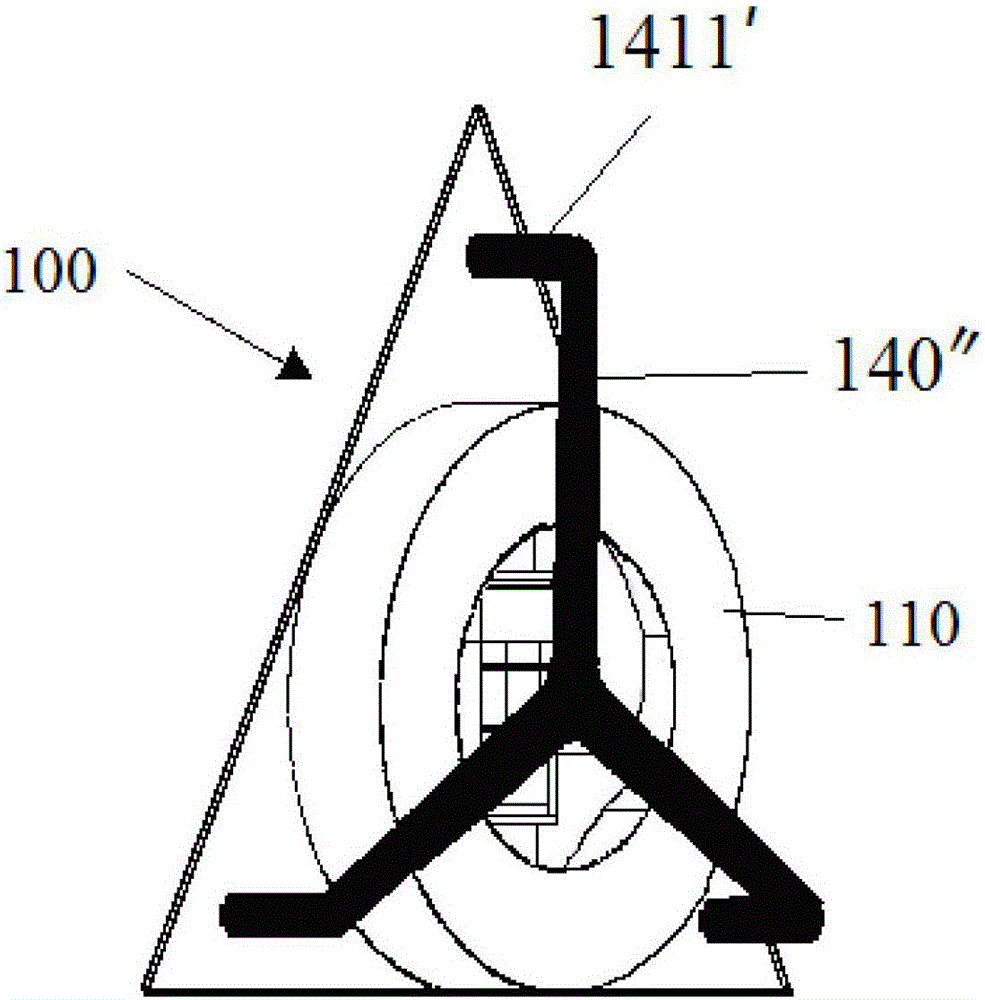
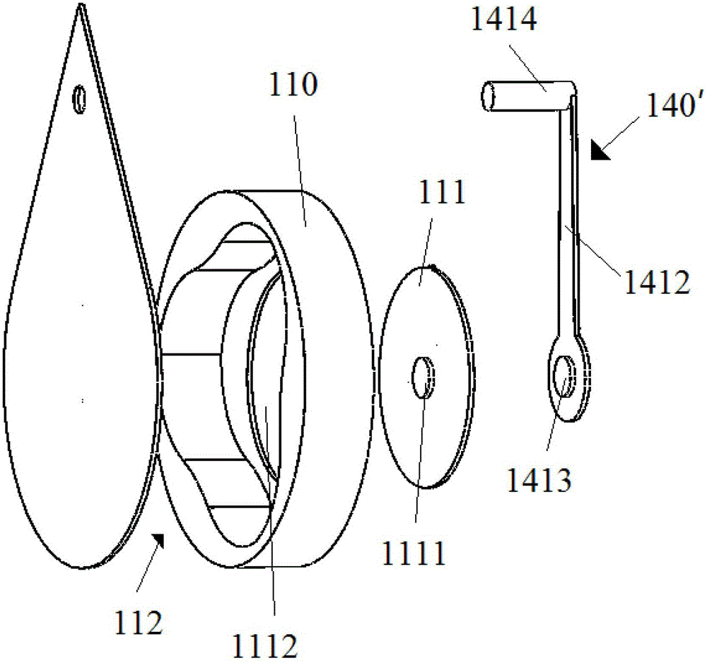
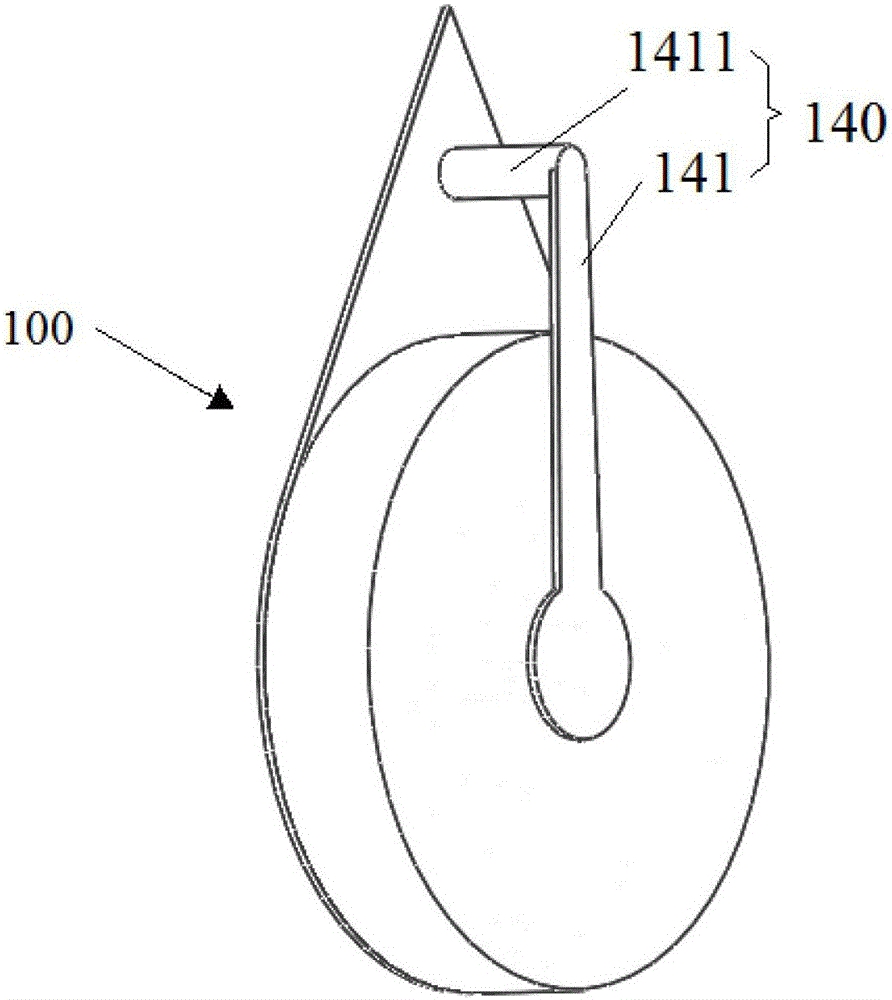
[0064] figure 1 Shown is a first embodiment of a descending device 100 of the present invention, the descending device 100 includes a rotatable sheave 110 for fixing the sheave 110 to a building structure (such as a building exterior wall, a balcony outer wall) of the first fixing part 140 (an embodiment 140" of the first fixing part 140 in the figure); a life-saving rope (not shown in the figure) is wound around the periphery of the sheave 110; specifically, one end of the life-saving rope is firmly Be tied to the wheel surface of the rope wheel 110, and the other end is provided with a lasso device (not shown) for firmly binding the body of the escapee; meanwhile, both sides of the wheel surface of the rope wheel 110 can also be provided with A baffle (not shown in the figure) to prevent the part of the lifeline wrapped around the sheave 110 from detaching from the sheave 110 .

[0065] refer to figure 1 or figure 2 The middle part of the sheave 110 is provided with an a...

no. 2 example

[0090] Figure 16 Shown is a second embodiment of a descending device 100 of the present invention, which includes a rotatable sheave 110 for fixing the sheave 110 to a building structure (such as a building exterior wall, a balcony outer wall) of the first fixing member 140 (not shown); the periphery of the sheave 110 is wound with a lifeline (not shown); specifically, one end of the liferope is firmly tied to the wheel surface of the sheave 110 , the other end is provided with a lasso device (not shown) for firmly binding the body of the escapee; at the same time, both sides of the sheave 110 wheel surface can also be provided with a noose device for preventing the life-saving rope from being wound on the sheave 110 A baffle (not shown) partially detached from the sheave 110.

[0091] refer to Figure 16 The sheave 110 is provided with an accommodating groove 112 whose opening is opposite to the building structure; the bottom surface of the accommodating groove 112 may be ...


PUM


Abstract

The invention provides a descent control device and a use method of the descent control device. The descent control device comprises a rotatable rope wheel (110) and a first fixing piece (140) used for fixing the rope wheel (110) on a building structure. A life line is wound on the periphery of the rope wheel (110). A containing groove (112) is formed in the middle of the rope wheel (110). A damping device (130) used for limiting the rotating speed of the rope wheel (110) is arranged in the containing groove (112). The descent control device is cheap and easy to use. By means of the damping device, under the conditions that no manual control or external force (such as electric power) assistance exists, an escaping person can land safely, controllably and fast.

Description

technical field [0001] The invention relates to a high-rise escape device, in particular to a descending device used for high-rise escape. Background technique [0002] With the development of the urbanization process, there are more and more high-rise buildings. The use of high-rise buildings not only improves the utilization rate of urban land and shows the style of the city, but also brings some safety hazards. For example, when disasters such as fires and earthquakes break out, people who are in high-rise buildings are generally difficult to escape. [0003] At present, high-rise buildings are rarely equipped with escape tools. When a disaster occurs, people on the upper floors of the building can only escape through safe passages or waiting for rescue. Under the circumstances, the life safety of the trapped personnel will be greatly threatened. In view of the above problems, people have developed escape tools such as descending devices, but the existing descending dev...

Claims


Application Information

Patent Timeline
Patent Type & Authority Patents(China)
IPC IPC(8): A62B1/10
Inventor 于杰
Owner 于杰
Why Eureka
Try Eureka