Tunnel intelligent lighting remote monitoring system

A remote monitoring system and intelligent lighting technology, applied in the field of tunnel intelligent lighting remote monitoring system, can solve problems such as white hole effect, hidden danger of driving safety, black hole effect, etc., achieve high lighting reliability, reduce maintenance workload, and reasonable lighting settings Effect

Inactive Publication Date: 2013-08-21
NANTONG ZHONGTIE HUAYU ELECTRICS
View PDF5 Cites 2 Cited by
  • Summary
  • Abstract
  • Description
  • Claims
  • Application Information

AI Technical Summary

Problems solved by technology

On the other hand, due to the continuous increase in the length of the tunnel, when the vehicle enters or exits the tunnel, the sudden change in brightness will cause the driver's vision to produce a "black hole effect" or "white hole effect", which will cause driving safety hazards. The problem is that when configuring lighting devices for road tunnels, it is necessary to consider the separate control of entrance lighting, interior lighting and exit lighting, and then consider energy-saving factors. The brightness of tunnel lighting at the entrance and exit sections during the day is high, and the lighting at night is correspondingly reduced. Specifically In general, the brightness of tunnel entrance and exit lighting should be determined according to the brightness outside the tunnel
In order to ensure the normal operation of the tunnel lighting, it is necessary to monitor the operation status of the lighting equipment in the tunnel in real time, which will bring a huge workload to the tunnel management personnel.

Method used


Image

  • Tunnel intelligent lighting remote monitoring system

Examples


Embodiment Construction

[0012] The content of the present invention will be further described in detail below in conjunction with the accompanying drawings and specific embodiments of the description:

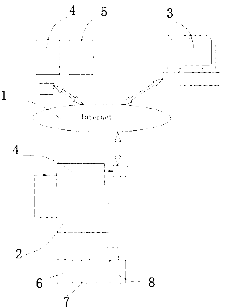
[0013] As shown in the figure is the functional block diagram of the tunnel intelligent lighting remote monitoring system, including the tunnel intelligent lighting controller 2, the remote monitoring device 5 and the network transmission system. The tunnel intelligent lighting controller 2 can simultaneously control multiple groups of lighting equipment, controlled by the tunnel intelligent lighting The PLC program controller of the device is controlled separately to realize the control of different brightness levels at the entrance and exit of the tunnel. Independent switch time parameters can be set for each group of lighting equipment. The switch light time can be different every day, and the operator does not need to It is necessary to input the switch light time parameters of each day, and only n...


PUM


Abstract

The invention discloses a tunnel intelligent lighting remote monitoring system used for tunnel lighting. The tunnel intelligent lighting remote monitoring system comprises a tunnel intelligent lighting controller, a remote monitoring device and a network transmission system. The tunnel intelligent lighting remote monitoring system is characterized in that the tunnel intelligent lighting controller controls a plurality of sets of lighting devices through a PLC at the same time, the remote monitoring device is composed of a communication circuit, a collecting circuit, a data processing circuit and a control circuit, the network transmission system is connected with a host machine in a tunnel through a local area network composed of an optical fiber self-healing ring network in the tunnel, a main optical-fiber MODEM and one or more sub optical-fiber MODEMs are connected through optical fibers to form the optical fiber self-healing ring network, and the host machine is connected to the Ethernet through a communication converter to transmit detection monitoring data in the tunnel to a central monitoring room. The tunnel intelligent lighting remote monitoring system has the advantages of being high in tunnel lighting reliability, reasonable in lighting arrangement, capable of carrying out remote monitoring and lowering maintenance workload, and energy-saving.

Description

technical field [0001] The invention relates to a lighting control system, in particular to a tunnel intelligent lighting remote monitoring system. Background technique [0002] With the advancement of society and the development of road traffic, tunnel construction is becoming more and more popular. Lighting is an important part of tunnel construction. Tunnel lighting can improve the road conditions in the tunnel, improve the visual enjoyment in the tunnel, and reduce driver fatigue. Improving tunnel capacity is an important facility to ensure transportation safety. If the failure of tunnel lighting equipment cannot be detected in time, it will endanger driving safety and cause accident hazards, resulting in major traffic accidents in the tunnel. In addition to subjective factors, the reasons for traffic accidents are objectively related to the lighting equipment in the tunnel. On the other hand, due to the continuous increase in the length of the tunnel, when the...

Claims


Application Information

Patent Timeline
Patent Type & Authority Applications(China)
IPC IPC(8): H05B37/02H05B37/03
CPCY02B20/40
Inventor 何秀平黄健华何小峰
Owner NANTONG ZHONGTIE HUAYU ELECTRICS
Why Eureka
Try Eureka