
Lamp control device and system

A technology for control devices and lamps, which is applied in the lighting field and can solve problems such as poor lighting reliability

Pending Publication Date: 2020-02-07
HUAIHUA VOCATIONAL & TECH COLLEGE
View PDF8 Cites 0 Cited by
  • Summary
  • Abstract
  • Description
  • Claims
  • Application Information

AI Technical Summary

Problems solved by technology

[0004] Based on this, it is necessary to provide a lamp control device and system for the problem of poor lighting reliability of traditional induction lighting lamps.

Method used


Image

  • Lamp control device and system
  • Lamp control device and system
  • Lamp control device and system

Examples


Embodiment Construction

[0024] In order to facilitate the understanding of the present application, the present application will be described more fully below with reference to the relevant drawings. Preferred embodiments of the application are shown in the accompanying drawings. However, the present application can be embodied in many different forms and is not limited to the embodiments described herein. On the contrary, the purpose of providing these embodiments is to make the understanding of the disclosure of the application more thorough and comprehensive.

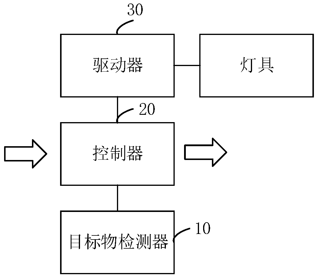
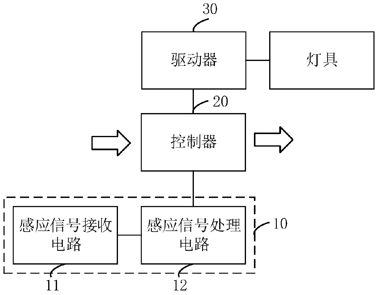
[0025] see figure 1 , a lamp control device, including a target detector 10, a controller 20 and a driver 30, the target detector 10 and the driver 30 are respectively connected to the controller 20, the driver 30 is used to connect the lamp, and the controller 20 is used to communicate with the adjacent The controller 20 of the lamp control device is connected, and the target object detector 10 is used to detect whether a target object e...


PUM


Abstract

The invention relates to a lamp control device and system. When a target object enters a lighting area, the target object can be detected and fed back to a controller, the controller sends a driving control signal to a driver, so a corresponding lamp enters a highlight lighting state. The controller can further send a wireless driving signal to a controller of an adjacent lamp control device, andthe adjacent lamp can further enter a highlight illumination state under the action of the wireless driving signal. Being similar to a current lamp control device, the adjacent lamp control device receives the wireless driving signal, the wireless driving signal is further sent to a controller of a lamp control device corresponding to the other lamps without high-brightness illumination, so the lamps corresponding to the lamp control device are sequentially controlled to enter a high-brightness illumination state by taking the lamp corresponding to the current lamp control device as the center. The lamp control device is advantaged in that the lamps can be controlled to enter the highlight state in sequence only through one-time target object detection operation, and the lamp control device is high in illumination reliability is achieved.

Description

technical field [0001] The present application relates to the technical field of lighting, in particular to a lamp control device and system. Background technique [0002] With the rapid development of science and technology, LED (Light Emitting Diode, Light Emitting Diode) lamps with superior energy-saving functions and service life are widely used in scenes such as parking lots and corridors for lighting. Induction lighting is an LED lamp with infrared or microwave induction function. Through infrared or microwave induction, it can basically achieve the effect of turning on the light when people come and turning off the light when people leave. It can save power and ensure the service life of LED lamps. [0003] However, for parking lot induction lights, individual lamps are individually controlled by induction. Since the car enters the parking lot with a certain speed, the sensing distance of the induction lights is limited, only 3-5 meters, plus the response time of the ...

Claims


Application Information

Patent Timeline
Patent Type & Authority Applications(China)
IPC IPC(8): H05B45/30
Inventor 杨洪军
Owner HUAIHUA VOCATIONAL & TECH COLLEGE
Learn More