
An intelligent display device and method based on modbus protocol

An intelligent display and protocol technology, applied in static indicators, transmission systems, program control, etc., can solve the problems of inflexible data display, less display data, and no intelligent learning and judgment functions

Inactive Publication Date: 2016-02-10
SHENYANG NORMAL UNIV
View PDF3 Cites 0 Cited by
  • Summary
  • Abstract
  • Description
  • Claims
  • Application Information

AI Technical Summary

Problems solved by technology

[0002] At present, under the guidance of the idea of ​​emphasizing the development from rough type to intensive type, various factories and mines continue to improve the automation of production technology. Some data on the site must be uploaded and displayed in real time. The usual display method is to upload the data to the industrial server. The display screen displays on-site data. This display method requires network wiring, and also requires related equipment such as industrial servers. The cost is high and the data display is inflexible.
Another way is to use a digital display table to display the data on site, but the brightness of the data displayed by the digital display table is not enough, the display is not obvious, and the number of displayed number groups is small, which is not conducive to long-distance observation by technicians. Flexibly adjust the display content and the size of the display screen, without intelligent learning and judgment functions

Method used


Image

  • An intelligent display device and method based on modbus protocol
  • An intelligent display device and method based on modbus protocol
  • An intelligent display device and method based on modbus protocol

Examples


Embodiment Construction

[0034] The specific implementation manners of the present invention will be described in detail below in conjunction with the accompanying drawings.

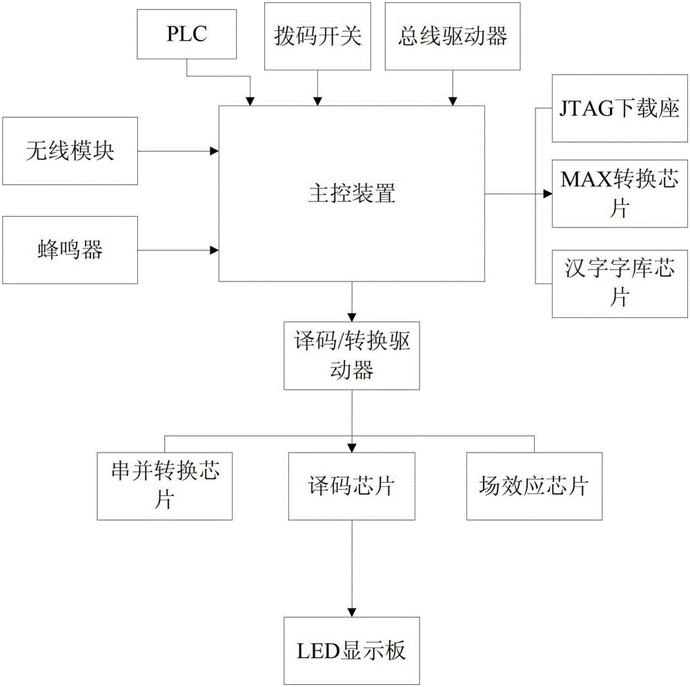
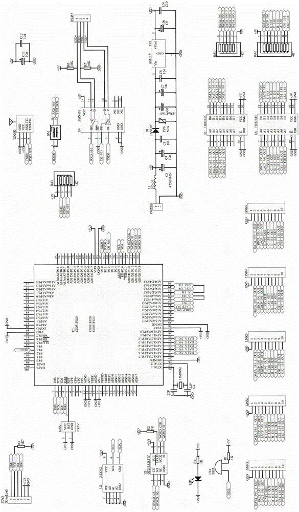
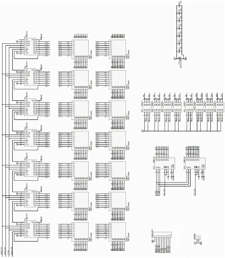
[0035] Such as figure 1 As shown, the intelligent display device based on the Modbus protocol includes PLC, main control device, bus driver, decoding / conversion driver, serial-to-parallel conversion chip, decoding chip, field effect chip, and LED display board installed on the industrial site;

[0036] The PLC installed on the industrial site is connected to the input terminal of the main control device, the industrial site data obtained by the PLC is transmitted to the input terminal of the main control device through the Modbus protocol format, and the output terminal of the main control device is connected to the input terminal of the decoding / converting driver. The output terminal of the decoding / converting driver is respectively connected to the input terminal of the serial-parallel conversion chip, the input terminal of th...


PUM


Abstract

Provided is an intelligent display device and method based on the Modbus protocol. The device comprises a PLC, a main control device, a bus driver, a decoding / converting driver, a series-parallel converting chip, a decoding chip, a field effect chip and an LED display board which are arranged on an industrial site. The PLC is connected with an input end of the main control device. The PLC obtains data of the industrial site and transmits the data to the input end of the main control device through the Modbus protocol format. An output end of the main control device is connected with an input end of the decoding / converting driver. An output end of the decoding / converting driver is respectively connected with an input end of the series-parallel converting chip, an input end of the decoding chip and an input end of the field effect chip. An output end of the series-parallel converting chip, an output end of the decoding chip and an output end of the field effect chip are connected to the LED display board. According to the intelligent display device and method, the industrial Modbus protocol format is used for data transmission, display luminance can be adjusted, a plurality of sets of data can be displayed according to practical needs, and an intelligent learning function and a judging warning function are achieved. The intelligent display device and method can be used for real-time intelligent-judging data displaying in major factories and mines.

Description

technical field [0001] The invention belongs to the field of automatic detection and control, and in particular relates to an intelligent display device and method based on the Modbus protocol. Background technique [0002] At present, under the guidance of the idea of ​​emphasizing the development from rough type to intensive type, various factories and mines continue to improve the automation of production technology. Some data on the site must be uploaded and displayed in real time. The usual display method is to upload the data to the industrial server. The display screen displays on-site data. This display method requires network wiring, and also requires related equipment such as industrial servers. The cost is high and the data display is inflexible. Another way is to use a digital display table to display the data on site, but the brightness of the data displayed by the digital display table is not enough, the display is not obvious, and the number of displayed numbe...

Claims


Application Information

Patent Timeline
Patent Type & Authority Patents(China)
IPC IPC(8): H04L29/06G05B19/418G05B19/042G09G3/32
CPCY02P90/02
Inventor 吴鹏王晨刘杰赵永翼李强于世东
Owner SHENYANG NORMAL UNIV
Learn More