Spray chamber hydraulic lifting device

A technology for lifting devices and spray booths, applied in the direction of lifting devices, etc., can solve the problems of unsafe lifting process, short service life, high use cost, etc., and achieve the effect of safe lifting process, reduced use cost and long service life

Inactive Publication Date: 2013-09-04
JIANGSU ZIQIANG COATING MACHINERY
View PDF0 Cites 8 Cited by
  • Summary
  • Abstract
  • Description
  • Claims
  • Application Information

AI Technical Summary

Problems solved by technology

[0002] In the painting industry, after the process of spraying the workpiece in the spray booth, it is necessary to use a lifting device to lift the workpiece. The existing lifting device needs to use four hydraulic cylinders. During use, the four hydraulic cylinders are very It is difficult to achieve synchronization, the lifting process is unsafe, the service life is short, and the use cost is high

Method used


Image

  • Spray chamber hydraulic lifting device
  • Spray chamber hydraulic lifting device

Examples


Embodiment Construction

[0010] The specific content of the present invention will be described in detail below in conjunction with the accompanying drawings and specific embodiments.

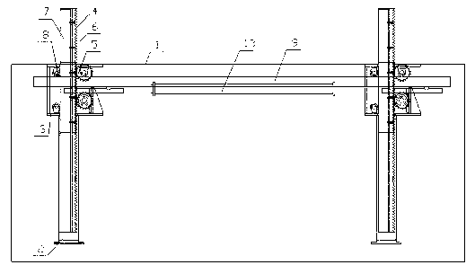
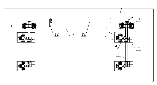
[0011] Such as figure 1 , figure 2 As shown, the hydraulic lifting device for the spray booth includes: four columns 2 arranged in the spray booth 1, a gear seat 3 is respectively arranged on the four columns 2, and a lifting rack 4 is arranged in the gear seat 3. The gear seat 3 is provided with a lifting gear 5 that cooperates with the lifting rack 4, and the lifting rack 4 is connected with the lifting plate 7 through a screw 6. In the gear seat 3, a pulley 8 that cooperates with one side of the lifting plate 7 is provided. The gear seat 3 is connected by a drive rod 9 and two connecting shafts 10, the drive rod 10 is arranged in the spray booth 1 through the guide seat 11, and the middle part of the drive rod 9 is connected to the cylinder 13 through the connecting plate 12. Connected, the two ends of the drivin...


PUM


Abstract

The invention discloses a spray chamber hydraulic lifting device capable of achieving synchronous lifting. The spray chamber hydraulic lifting device comprises four stand columns arranged in a spray chamber. Gear bases are arranged on the four stand columns respectively, lifting racks are arranged inside the gear bases, lifting gears matched with the corresponding racks are arranged in the gear bases, the lifting racks are connected with lifting plates through bolts, pulleys matched with one sides of the lifting plates are arranged inside the gear bases, the gear bases are connected through a driving rod and two connecting shafts, the driving rod is arranged inside the spray chamber through a guiding base, the middle portion of the driving rod is connected with an air cylinder through a connecting plate, the two ends of the driving rod are connected with transmission gears and the connecting shafts respectively, and the lifting gears are arranged on the connecting shafts. The spray chamber hydraulic lifting device has the advantages that the four lifting racks move synchronously, the lifting process is safe, service life is long, and using cost is reduced.

Description

technical field [0001] The invention relates to painting equipment, in particular to a hydraulic lifting device for a painting booth. Background technique [0002] In the painting industry, after the process of spraying the workpiece in the spray booth, it is necessary to use a lifting device to lift the workpiece. The existing lifting device needs to use four hydraulic cylinders. During use, the four hydraulic cylinders are very It is difficult to achieve synchronization, the lifting process is unsafe, the service life is short, and the use cost is high. Contents of the invention [0003] The technical problem to be solved by the present invention is to provide a hydraulic lifting device for a spray booth that can realize synchronous lifting. [0004] In order to solve the above-mentioned technical problems, the technical solution adopted by the present invention is as follows: four columns arranged in the spray painting room, gear seats are respectively arranged on the ...

Claims


Application Information

Patent Timeline
Patent Type & Authority Applications(China)
IPC IPC(8): B66F3/46B66F3/04B66F3/24
Inventor 吕海波陈燕
Owner JIANGSU ZIQIANG COATING MACHINERY
Why Eureka
Try Eureka