Wheel dolly for small aircraft

a technology for small aircraft and dolly, which is applied in the direction of wheel mounting apparatus, instruments, and static/dynamic balance measurement, etc. it can solve the problems of not being particularly adapted to difficult if not impossible to get the horizontally disposed arms sufficiently under the tire to be able, and prior art wheel dollies are therefore not particularly adapted for use on flat tires attached to aircraft. , to achieve the effect of quick and safe taxation

Active Publication Date: 2015-08-18
WINTERS MASON JESS
View PDF65 Cites 7 Cited by
  • Summary
  • Abstract
  • Description
  • Claims
  • Application Information

AI Technical Summary

Benefits of technology

[0007]Accordingly, the present invention provides a wheel dolly particularly configured for temporarily supporting and lifting a tire of a small airplane during taxi. The wheel dolly is configured for insertion beneath a flat tire still attached to an airplane and safely lifts the flat tire off the ground. Once the flat tire has been lifted and supported by the wheel dolly, the airplane can then be quickly and safely taxied from the runway, as by towing with a tug.
[0008]The wheel dolly may be configured to lift a wheel of an airplane that weighs up to about 8400 pounds having wheel diameters up to about 30 inch diameter and ten inch width. Of course, the wheel dolly of the present invention could be configured to lift much heavier airplanes having larger tires. In any case, a single person can safely and easily operate the wheel dolly of the present invention.
[0011]In another embodiment, the wheel dolly further comprises a hand pump in fluid communication with the ram for pressurizing the ram thus causing the ram to extend in length in order to pivot the first and second tire support structures relative to the first and second side frame members, respectively.
[0013]In still another embodiment, the telescopic frame structure comprises a first telescopic frame member and a second telescopic frame member at least partially inserted with in the first telescopic frame member. The second telescopic frame member is longitudinally movable relative to the first telescopic frame member in order to increase or decrease the length of the telescopic frame structure.
[0014]In yet another embodiment, the actuator comprises a threaded actuator assembly coupled to and between the first telescopic frame member and the second telescopic frame member such that rotation of the threaded actuator causes the telescopic frame structure to lengthen or shorten depending on the direction of rotation of the threaded actuator.

Problems solved by technology

Moreover, such prior art wheel dollies are not particularly adapted for lifting a flat tire that is still attached to a vehicle in which case the weight of the vehicle makes it difficult if not impossible to get the horizontally disposed arms sufficiently under the tire to be able to raise it from the ground.
Such prior art wheel dollies are thus not particularly adapted for use on a flat tire attached to an aircraft.
Such use could result in pinching the tire, in being unstable during movement of the aircraft and / or in damaging to the aircraft.
Moreover, such prior art wheel dollies are not particularly adapted to be driven over a distance under power of the vehicle.
A particular problem that exists at airports that allow for landing of small aircraft, such as single or dual engine airplanes known in the art, is that it is rather common for such small aircraft to experience a flat tire upon landing.
This is often due to a harder than usual landing that causes one or more of the tires of the airplane to blow.
Obviously, the problem with such a situation is that the runway where the airplane is parked while the flat tire is being replaced cannot be used.
At smaller airports, especially single runway airports, this presents a particularly problematic and potentially dangerous situation.
That is, if a runway of a single runway airport is closed and another airplane requires an emergency landing, there may be no safe place for the airplane to land.

Method used


Image

  • Wheel dolly for small aircraft
  • Wheel dolly for small aircraft
  • Wheel dolly for small aircraft

Examples


Embodiment Construction

[0030]Those of ordinary skill in the art will realize that the following description of the present invention is illustrative only and not in any way limiting. Other embodiments of the invention will readily suggest themselves to such skilled persons, including without limitation combinations of features of the illustrated embodiments.

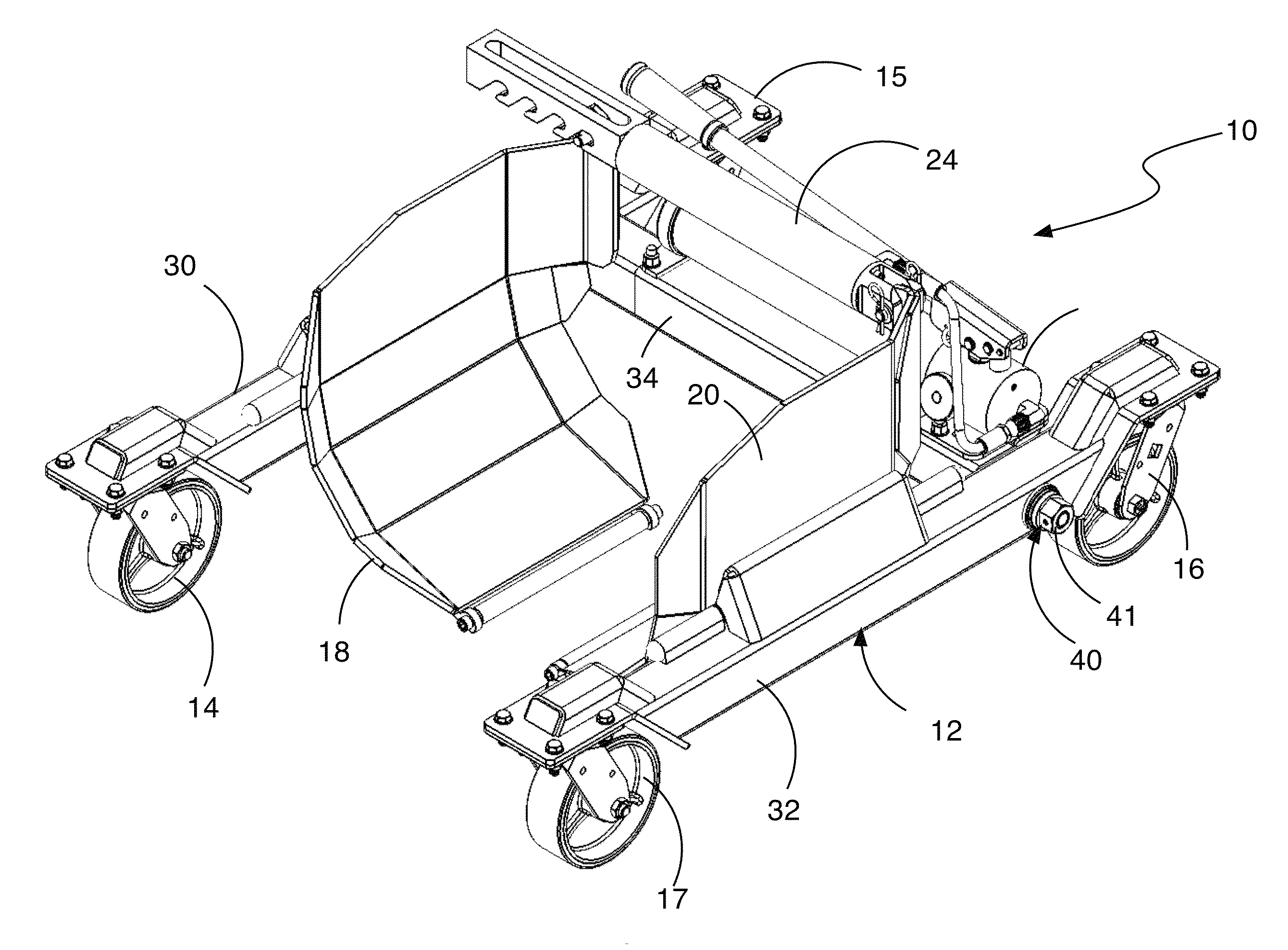
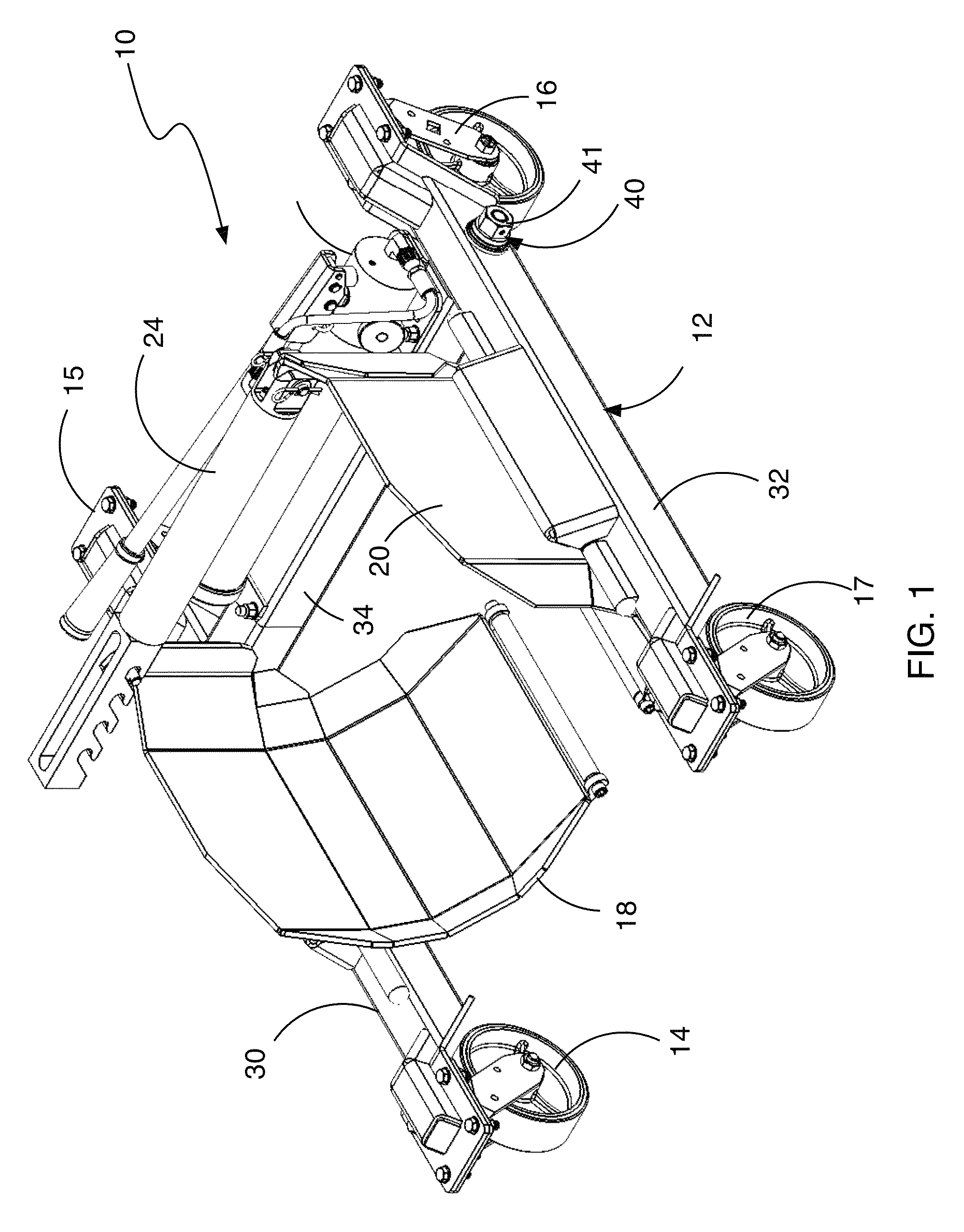
[0031]FIG. 1 illustrates a wheel dolly, generally indicated at 10, in accordance with the principles of the present invention. The wheel dolly 10 is particularly configured for temporarily supporting and lifting a tire of a small airplane during taxi. The wheel dolly 10 is more importantly configured to lift and support a tire of a small airplane that has become flat upon landing and to allow the airplane to be taxied from a runway while the wheel dolly 10 is supporting the tire of the airplane.

[0032]The wheel dolly 10 is comprised of a three-sided, rectangular frame structure 12 that defines four corners, each of which is supported by one of a plurali...


PUM


Abstract

A wheel dolly for lifting and transporting a flat tire attached to an aircraft is comprised of a frame assembly having first and second laterally spaced frame members and a telescopic frame structure interposed between the laterally spaced frame members. A pair of tire scoops are pivotally coupled the frame assembly. An actuator is coupled between the tire scoops to pivot the tire scoops relative to the frame assembly in order to raise the tire scoops. A plurality of castors is coupled to the frame assembly to allow the frame assembly to roll in any direction.

Description

CROSS-REFERENCE TO RELATED APPLICATIONS[0001]This application claims priority to U.S. Provisional Patent Application No. 61 / 679,500, filed Aug. 3, 2012, the entirety of which is incorporated by reference.FIELD OF THE INVENTION[0002]The present invention relates generally to devices commonly referred to as “wheel dollies”. More specifically, the present invention relates to wheel dollies particularly adapted for use with small aircraft that allow a small aircraft with a flat tire to be taxied from the runway.STATE OF THE RELATED ART[0003]Various wheel dollies have been known in the art for lifting and moving vehicular wheels. The wheel dollies may be used separately, in pairs or in any number corresponding to the number of wheels on a vehicle. Wheel dollies have been described in the art as consisting of tow horizontal arms that are brought together toward the perimeter of a wheel. As the two arms are sufficiently brought together, the wheel is lifted from the ground and thus support...

Claims


Application Information

Patent Timeline
Patent Type & Authority Patents(United States)
IPC IPC(8): B60B30/10B60B30/02
CPCB60B30/02B60B30/10B60B2900/351
Inventor WINTERS, MASON JESS
Owner WINTERS MASON JESS
Why Eureka
Try Eureka