Fuel assembly top nozzle repair sleeve and method for repairing a fuel assembly

a fuel assembly and top nozzle technology, applied in nuclear engineering problems, nuclear elements, greenhouse gas reduction, etc., can solve the problems of stress corrosion cracking, fuel assembly deformation over time, increasing the economic cost of the reactor owner,

Inactive Publication Date: 2009-06-23
AREVA NP INC
View PDF55 Cites 7 Cited by
  • Summary
  • Abstract
  • Description
  • Claims
  • Application Information

AI Technical Summary

Benefits of technology

[0008]It is an objective of the present invention to provide a method and device to repair damaged nuclear fuel assemblies such that a damaged fuel assembly may be lifted safely.
[0009]It is also an objective of the present invention to provide a method and device to provide a permanent repair for fuel assemblies which exhibit structural defects, such as stress corrosion cracking, between the top nozzle, the guide thimble sleeves and the guide thimble.
[0010]It is furthermore an objective of the present invention to provide an economically efficient method and device for repair of degraded fuel assemblies such that the repair may be accomplished quickly and efficiently.

Problems solved by technology

Industry experience has discovered that fuel assemblies can degrade over time near the top nozzle section of the fuel assembly.
Industry experience has identified that a connection established between the top nozzle and the guide thimble, often in the form of a guide thimble sleeve, can be prone to stress corrosion cracking through continued fuel assembly use.
Degradation of the structural support established between the top nozzle and the guide thimbles prevents movement of the degraded fuel assembly as the fuel assembly may not be structurally adequate to lift its own weight.
Current repair alternatives to correct stress corrosion cracking often delay nuclear reactor restart, thereby increasing the economic costs for the reactor owner.

Method used


Image

  • Fuel assembly top nozzle repair sleeve and method for repairing a fuel assembly
  • Fuel assembly top nozzle repair sleeve and method for repairing a fuel assembly
  • Fuel assembly top nozzle repair sleeve and method for repairing a fuel assembly

Examples


second embodiment

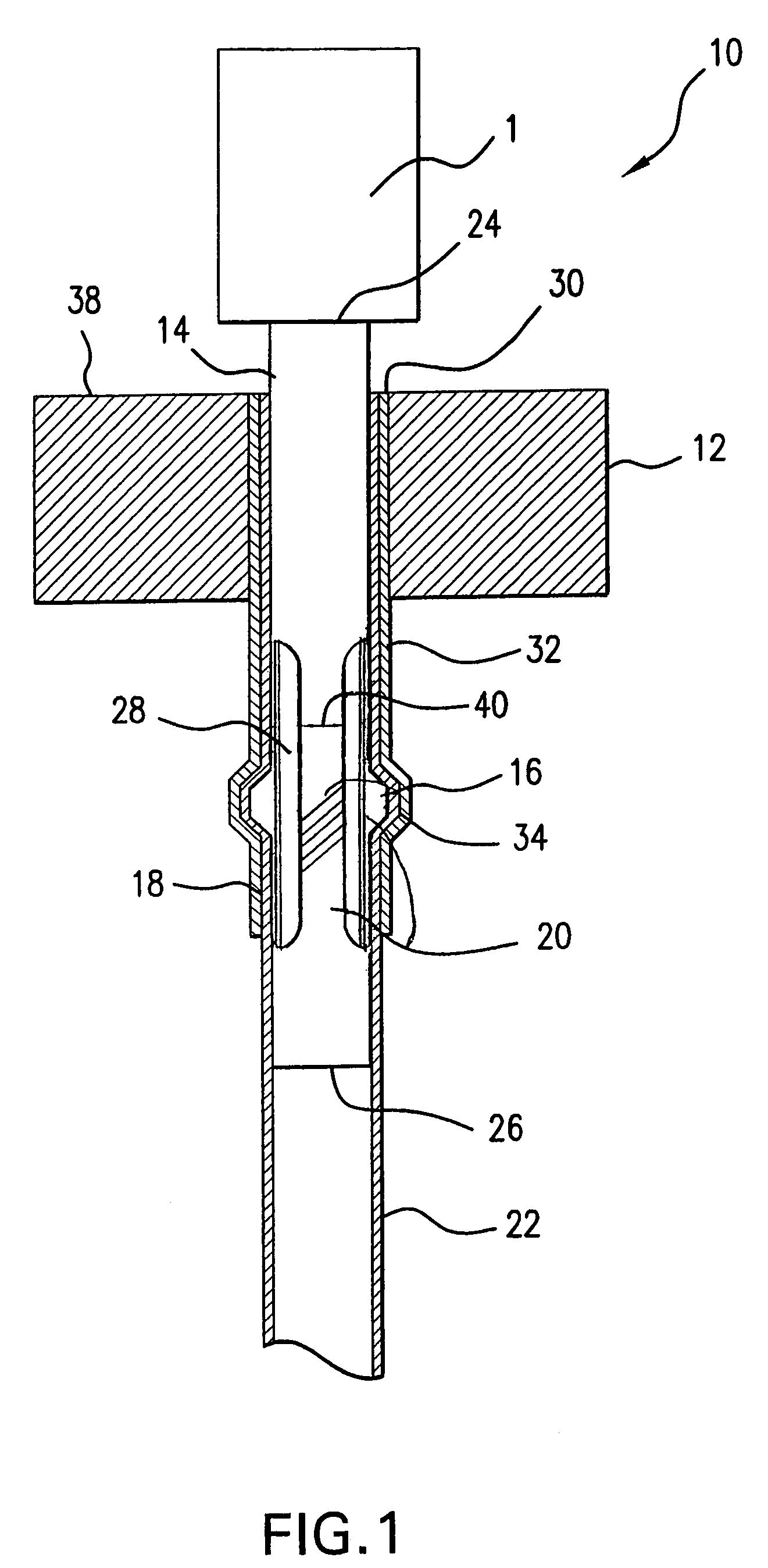
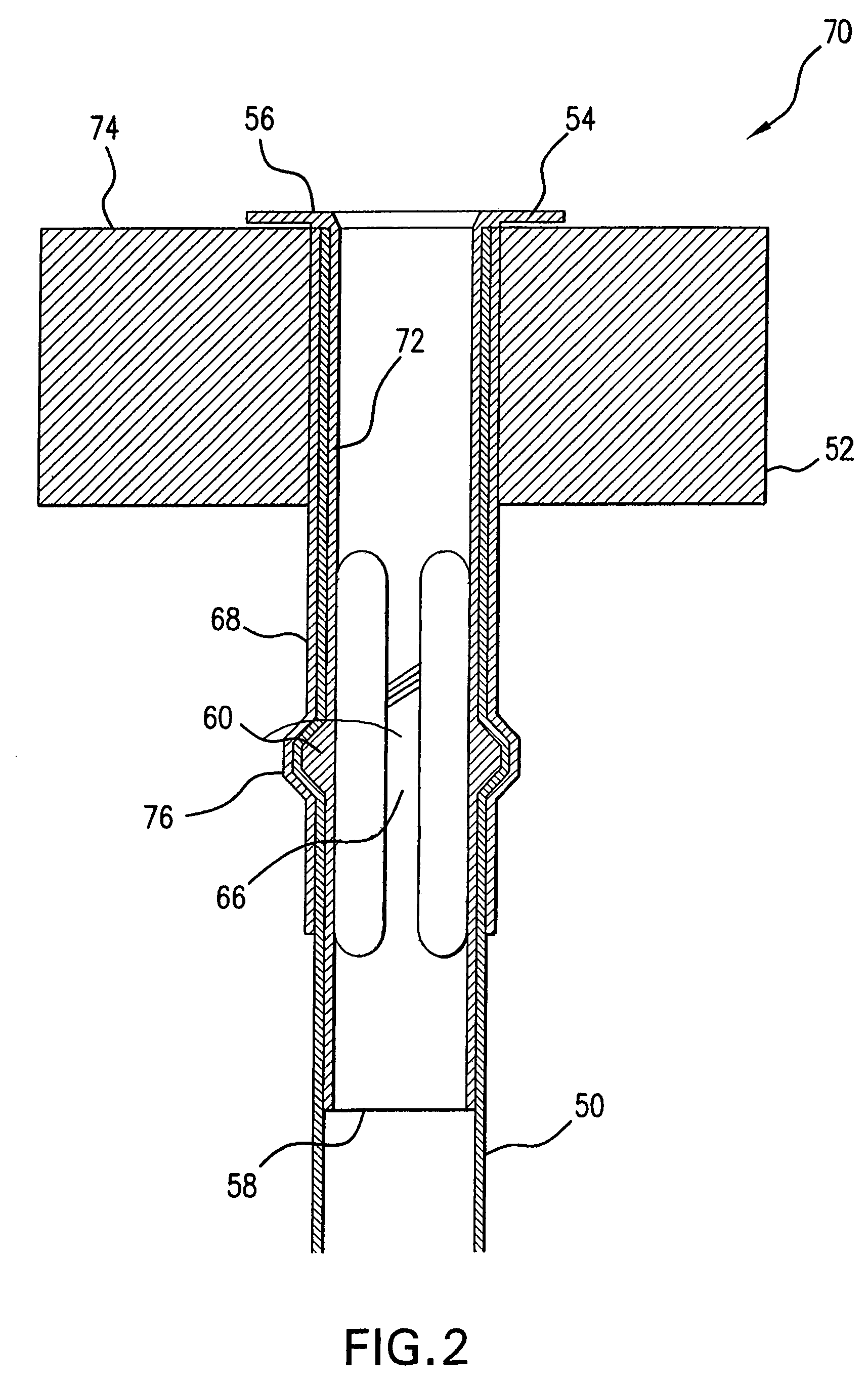
[0022]Referring to FIG. 2, a repair sleeve 70 is illustrated. The repair sleeve 70 has a shaft 72. The repair sleeve 70 has a first end 56 and a second end 58. The second end 58 is configured to be inserted into a guide thimble opening of the top nozzle 52. The first end 56 of the repair sleeve 70 may be configured with a lapped edge 54 which extends beyond an external top surface 74 of the top nozzle 52. The lapped edge 54 may have an external diameter which is greater in circumference than the external diameter of the opening of the top nozzle 52 for the guide thimble 50. Although illustrated as a circular lapped edge 54, other configurations are possible, such as square, hexagonal, or octagonal for example. The lapped edge 54 may be finally configured while the repair sleeve 70 is installed in the top nozzle 52. Alternatively, the lapped edge 54 may be preformed prior to installation of the repair sleeve 70.

first embodiment

[0023]A projection 60 may be formed on a tendon 66 of the repair sleeve 70. The length of the tendon 66 may be chosen such that the projection 60 is placed in a dimple area 76 formed from the swaged area 78 of the guide thimble 50 and the guide thimble sleeve 68. The contact established between the projection 60 and the dimple area 76 may be configured to allow a transfer of a specified amount of force. Similar to the first embodiment, the repair sleeve 70 may be modified such that the overall length of the sleeve 70 may reach multiple dimple areas in the guide thimble 50. The projection 60 may be formed in any geometric configuration such as a hemispherical, trapezoidal or other arrangement.

[0024]Referring to FIG. 3, a graph of the structural capacity of the repair sleeve 10 is illustrated. The vertical axis of the graph represents load carrying capacity of the repair sleeve 10. The horizontal axis of the graph represents overall position of the repair sleeve. As illustrated, the r...


PUM


Abstract

A method and device to repair nuclear fuel assembly structural defects in the top nozzle to guide thimble connection, wherein the device includes a repair sleeve comprising tendons configured to deflect to allow establishment of a structural connection between a projection on each tendon and a dimple area of a guide thimble.

Description

FIELD OF THE INVENTION[0001]The present invention relates to handling of fuel assemblies for nuclear reactors. More specifically, the present invention relates to a method and device for installing a top nozzle repair sleeve in a nuclear fuel assembly to assist in structural transfer of forces when the fuel assembly is lifted.BACKGROUND INFORMATION[0002]Present-day nuclear power reactors use fuel in the form of fuel assemblies. The fuel assemblies usually are comprised of a uranium dioxide matrix, generally in the shape of pellets, stacked end-to-end. The stacked pellets are clad on their respective exterior by a zirconium metal alloy which prevents direct contact between the uranium dioxide pellets and reactor coolant. The fuel rods formed by the pellets cladded by the zirconium metal alloy are placed in a structural skeleton in a side by side arrangement to allow a dense packing of nuclear material. At the top and bottom of the fuel assembly, respective top and bottom nozzles are ...

Claims


Application Information

Patent Timeline
Patent Type & Authority Patents(United States)
IPC IPC(8): G21C19/00G21C13/00G21C19/02G21C19/19G21C19/33
CPCG21C3/334G21Y2002/201G21Y2002/202Y02E30/40G21Y2004/301G21Y2004/40G21Y2004/504G21Y2002/402Y02E30/30
Inventor PABIS, GEORGE S.PUGH, ANTHONY A.KING, RAYMOND A.CLARK, DAREL R.
Owner AREVA NP INC
Why Eureka
Try Eureka