Lifting support for portable electronic device and portable electronic device
A technology of portable electronic equipment and lifting brackets, which is applied in the direction of mechanical equipment, machines/stands, supporting machines, etc. It can solve the problems that the brackets cannot have good portability at the same time, and the height adjustment of the display screen cannot be realized, so as to improve the visual experience. The effect of compact structure and simple unfolding process
- Summary
- Abstract
- Description
- Claims
- Application Information
AI Technical Summary
Problems solved by technology
Method used
Image
Examples
Embodiment 1
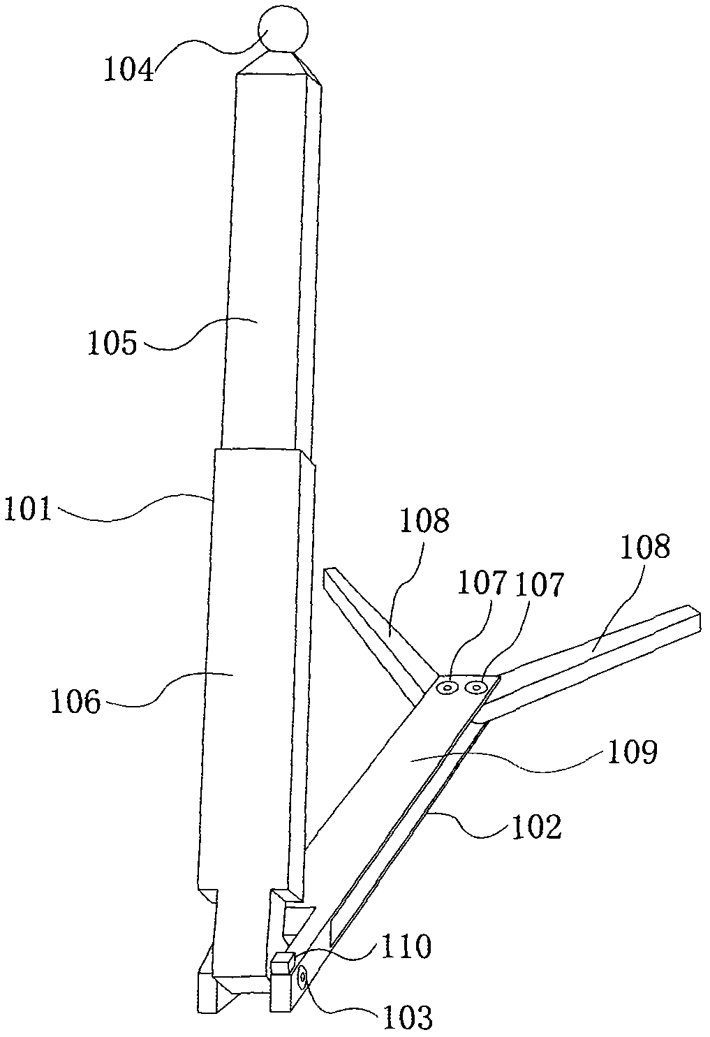
[0030] Example 1, please refer to figure 1 , which is a schematic structural diagram of the main body of the liftable support, and the container of the liftable support is not shown. The main body of the liftable support in the figure includes: a movable pull rod 101 , a bifurcated structure base 102 , and a rotating shaft 103 . The rotating shaft 103 belongs to the movable connection part.
[0031] Movable pull rod 101 belongs to telescopic bracket, and one end of movable pull rod 101 has circular connecting protrusion 104, and the other end is movably connected to bifurcated structure base 102 through rotating shaft 103, and movable pull rod 101 is specifically composed of inner sleeve rod 105 and outer sleeve rod in this embodiment. 106, through the relative sliding of the inner sleeve rod 105 and the outer sleeve rod 106 to achieve the telescopic effect, and realize the height adjustment of the display screen of the portable electronic device.
[0032] The bifurcated str...
Embodiment 2
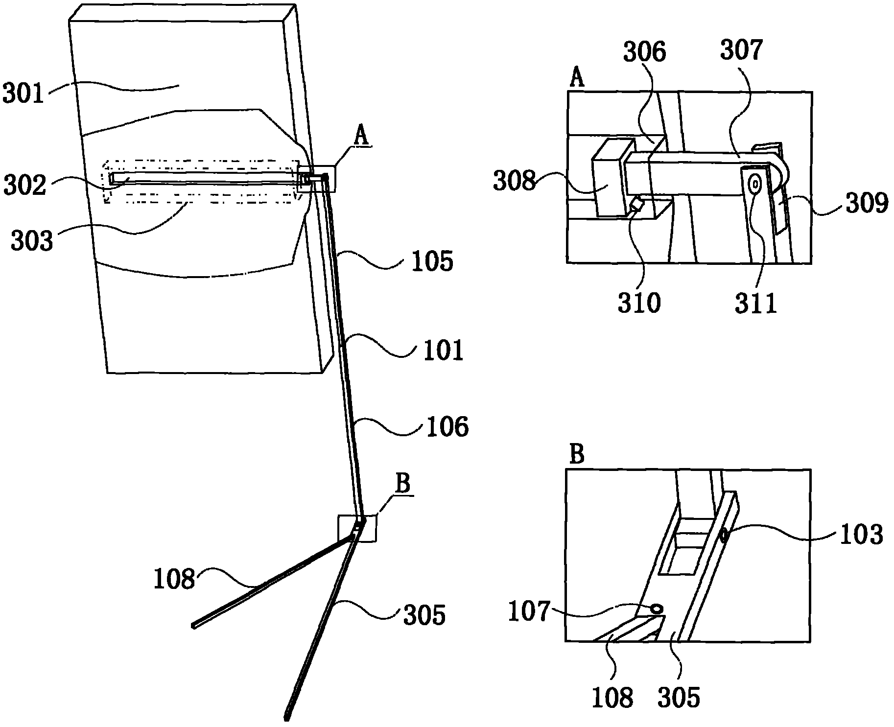
[0045] Example 2, please refer to image 3, which is a schematic structural diagram of a tablet computer with a liftable stand. The portable electronic device is specifically a tablet computer 301, which has a liftable bracket main body, a movable rod storage groove 302, and a movable base storage groove 303 (depicted by dotted lines). 308 provides a sliding track, and the movable base receiving groove 303 is used for accommodating the movable base. In this embodiment, the movable pull rod 101 is connected to the main body of the tablet computer 301 through a sliding member 308, and has an inner sleeve rod 105, an outer sleeve rod 106, and a connecting piece for switching between horizontal and vertical screens. The adjustment direction of the horizontal and vertical screen switching connector is the left and right directions, and is used to realize the switching between the vertical screen and the horizontal screen of the portable electronic device, which further satisfies t...
Embodiment 3
[0050] Embodiment three, Figure 4 It is a structural schematic diagram of a mobile phone with a liftable stand. The liftable stand is specifically a semi-built-in liftable stand. The semi-built-in means that part of the container structure of the liftable stand is not wrapped by a shell. Such as Figure 4 As shown, the mobile phone 401 in the figure has a main body of a liftable bracket and a receiving groove 402 of a "C"-shaped rod base. The main body of the liftable support includes two movable pull rods 101, a "C"-shaped rod base 403, and two rotating shafts 103. The figure shows the lower half of the movable pull rod 101, and the upper half of the movable pull rod 101 is built into the In the body of the mobile phone 401, the "C"-shaped bar base 403 belongs to the base structure. The "C"-shaped pole base receiving groove 402 is a semi-built-in container for the liftable support, which is used to accommodate the "C"-shaped pole base 403 of the main body of the liftable s...
PUM
 Abstract
Description
Claims
Application Information
 - R&D
- Intellectual Property
- Life Sciences
- Materials
- Tech Scout
- Unparalleled Data Quality
- Higher Quality Content
- 60% Fewer Hallucinations
Browse by: Latest US Patents, China's latest patents, Technical Efficacy Thesaurus, Application Domain, Technology Topic, Popular Technical Reports.
© 2025 PatSnap. All rights reserved.Legal|Privacy policy|Modern Slavery Act Transparency Statement|Sitemap|About US| Contact US: help@patsnap.com


