Air-conditioning guide mechanism and air conditioner
A technology of air guide mechanism and air conditioner indoor unit, which is applied in the direction of airflow control element, etc., can solve the problems of single fixed air supply or swing air supply mode, complex air guide structure of air conditioner, and inability to select air supply, etc., to meet individual needs , Simple structure, comfortable air supply
- Summary
- Abstract
- Description
- Claims
- Application Information
AI Technical Summary
Problems solved by technology
Method used
Image
Examples
Embodiment 1
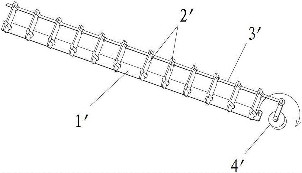
[0034] see Figure 5 Embodiment 1 of the present invention provides an air-conditioning air guiding mechanism including a base 1, an air outlet assembly 2 and a driving part 3, and the air outlet assembly 2 includes a first connecting rod 211, a second connecting rod 212 and a And a plurality of air guide louvers 22 on the second connecting rod 212, the flexible connection of the first end of the first connecting rod 211 and the first end of the second connecting rod 212 is hinged, specifically, can be in the first The first end of the connecting rod 211 is provided with a connecting hole 2111, and the first end of the second connecting rod 212 is provided with a connecting shaft 2121, and the connecting hole 2111 is set on the connecting shaft 2121 to realize the hinge; as an alternative, also Conversely, the connecting shaft 2121 is arranged on the first connecting rod 211, and the connecting hole 2111 is arranged on the second connecting rod 212; and the second end of the f...
Embodiment 2
[0040] The difference between the present embodiment and the first embodiment lies in the structure of the slider and the connection method between the slider and the connecting rod. refer to Figure 9 In this embodiment, the slider 41" includes a slider 412" and a protruding shaft 411", the slider 412" is spherical, the slider 41" can be integrally formed with the second end of the first connecting rod 211, or Detachable connection. The protruding shaft 411 "and the sliding body 412" are preferably integrally formed, but they can also be connected together after being formed separately, and the structure of the connecting slide hole 11 is the same as that in Embodiment 1. In this example, the sliding block 41 The spherical sliding body of "can slide in the connecting sliding hole 11 flexibly and is not easily interfered. Other structures are the same as those in Embodiment 1, and will not be repeated here.
Embodiment 3
[0042] The structure of this embodiment is not shown, please refer to Figure 5 It should be understood that the difference between the third embodiment and the first embodiment is that: the second end of the first connecting rod 211 is hinged to the base 1, specifically a connecting column (not shown) can be provided on the base 1, and the first The second end of the connecting rod 211 is provided with a connecting hole 2110, and the connecting hole 2110 is sleeved on the connecting column to realize hinge connection, so that the first connecting rod 211 can rotate around the connecting column and its second end as a whole; The first end of the connecting rod 211 is provided with a guide sliding hole (not shown) with a certain length, and the first end of the second connecting rod 212 is provided with a sliding post (not shown) adapted to the guiding sliding hole. The sliding column can slide along the length direction of the sliding hole in the sliding hole, so as to realize...
PUM
 Abstract
Description
Claims
Application Information
 - R&D
- Intellectual Property
- Life Sciences
- Materials
- Tech Scout
- Unparalleled Data Quality
- Higher Quality Content
- 60% Fewer Hallucinations
Browse by: Latest US Patents, China's latest patents, Technical Efficacy Thesaurus, Application Domain, Technology Topic, Popular Technical Reports.
© 2025 PatSnap. All rights reserved.Legal|Privacy policy|Modern Slavery Act Transparency Statement|Sitemap|About US| Contact US: help@patsnap.com


