End stamping mechanism

A technology of stamping head and frame, applied in the direction of electrical components, circuits, connections, etc.

Active Publication Date: 2013-09-11
南京鼎典科技有限公司
View PDF7 Cites 1 Cited by
  • Summary
  • Abstract
  • Description
  • Claims
  • Application Information

AI Technical Summary

Problems solved by technology

[0004]The stamping head used for end punching on automated electronic wire processing machinery is usually adjusted by rotating the screw to adjust the height of the punching head, and the height of the screw will be adjusted after several rotations. A certain amount of wear, long-term wear will lead to problems such as jamming and enlarged gaps

Method used


Image

  • End stamping mechanism
  • End stamping mechanism

Examples


Embodiment Construction

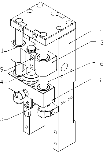
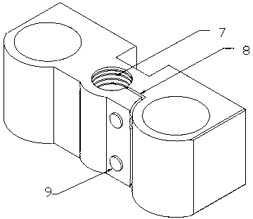
[0014] like Figure 1 to Figure 2 As shown, a stamping end mechanism includes: frame 1, die head 2, die head upper adjustment block 3, die head torsion bar 4, stamping head 5, two die head guide posts 6, the two die heads The upper and lower ends of the guide pillar 6 are fixed on the frame 1, the die head 2 is arranged on the two die head guide pillars 6, and the upper adjustment block 3 of the die head is also arranged on the two die head guide pillars 6 and is above the die head 2. One end of the head torsion rod 4 is fixed on the die head 2, the other end of the die head torsion rod 4 is fixed on the upper adjustment block 3 of the die head, and the die head torsion rod 4 and the upper die head adjustment block 3 are threadedly connected. The stamping head 5 is fixed on the die head 2, and it is characterized in that: an opening 8 is arranged in the axial direction on the threaded hole 7 matched by the adjusting block 3 on the die head and the torsion rod 4 of the die head...


PUM


Abstract

The invention relates to the field of machinery for electronic wires, in particular to an end stamping mechanism which comprises a framework, a die head, a die head upper adjusting block, a die head torque adjusting rod, a stamping head and two die head guide columns. An opening is axially formed in a threaded hole, which is matched with the die head torque adjusting rod, of the die head upper adjusting block, a certain distance is reserved between two surfaces of the opening in a natural state, and screws are arranged in a direction perpendicular to the surfaces of the opening. The end stamping mechanism with the structure has the advantages that a tightness adjusting mechanism is arranged between the die head upper adjusting block and the die head torque adjusting rod, is released at first when the die head torque adjusting rod needs to rotate to adjust the height of the stamping head, and is screwed down after the height of the stamping head is determined, so that threads of the die head torque adjusting rod are protected, and damage can be reduced.

Description

technical field [0001] The invention relates to the field of electronic wire rod machinery, in particular to a stamping end-making mechanism. Background technique [0002] The application of automated machinery has brought an unprecedented increase in productivity, and more and more automated machinery is used in the manufacturing industry, and the same is true in the field of electronic wire manufacturing. The electronic cable is not only thin but also dense. If it is processed by hand, it will be a very complicated process to measure the length, cut off, peel off the rubber at both ends, separate the thin wires of the cable, and give each cable a terminal. Waste of time and quality is not guaranteed. Later, people gradually used automated machinery instead of manual labor to complete the electronic wiring process from beginning to end, which greatly improved productivity. [0003] However, the current automated electronic wire processing machinery still has problems such...

Claims


Application Information

Patent Timeline
Patent Type & Authority Applications(China)
IPC IPC(8): H01R43/048
Inventor 赵维
Owner 南京鼎典科技有限公司
Why Eureka
Try Eureka