Electronic apparatus

A technology for electronic equipment and frames, applied in optics, instruments, projection devices, etc., can solve problems such as damaging the appearance of projection display devices, and achieve the effect of improving operability

Active Publication Date: 2015-07-08
NEC DISPLAY SOLUTIONS LTD
View PDF7 Cites 1 Cited by
  • Summary
  • Abstract
  • Description
  • Claims
  • Application Information

AI Technical Summary

Problems solved by technology

[0004] Therefore, since the cable group pulled out from the connection terminal portion of the housing can be seen, the appearance of the projection display device is impaired.

Method used


Image

  • Electronic apparatus
  • Electronic apparatus
  • Electronic apparatus

Examples


Embodiment Construction

[0033] Hereinafter, specific embodiments of the present invention will be described with reference to the drawings.

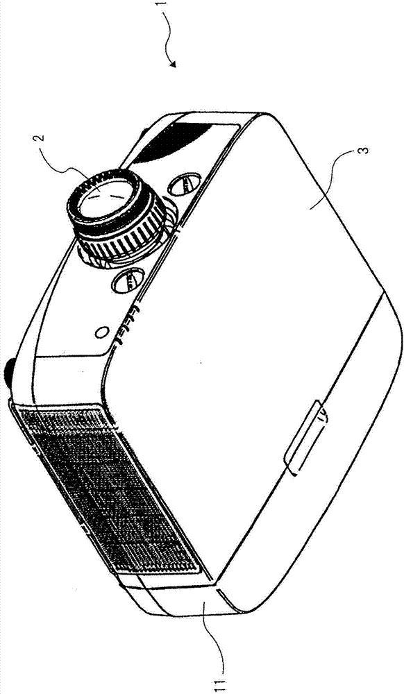
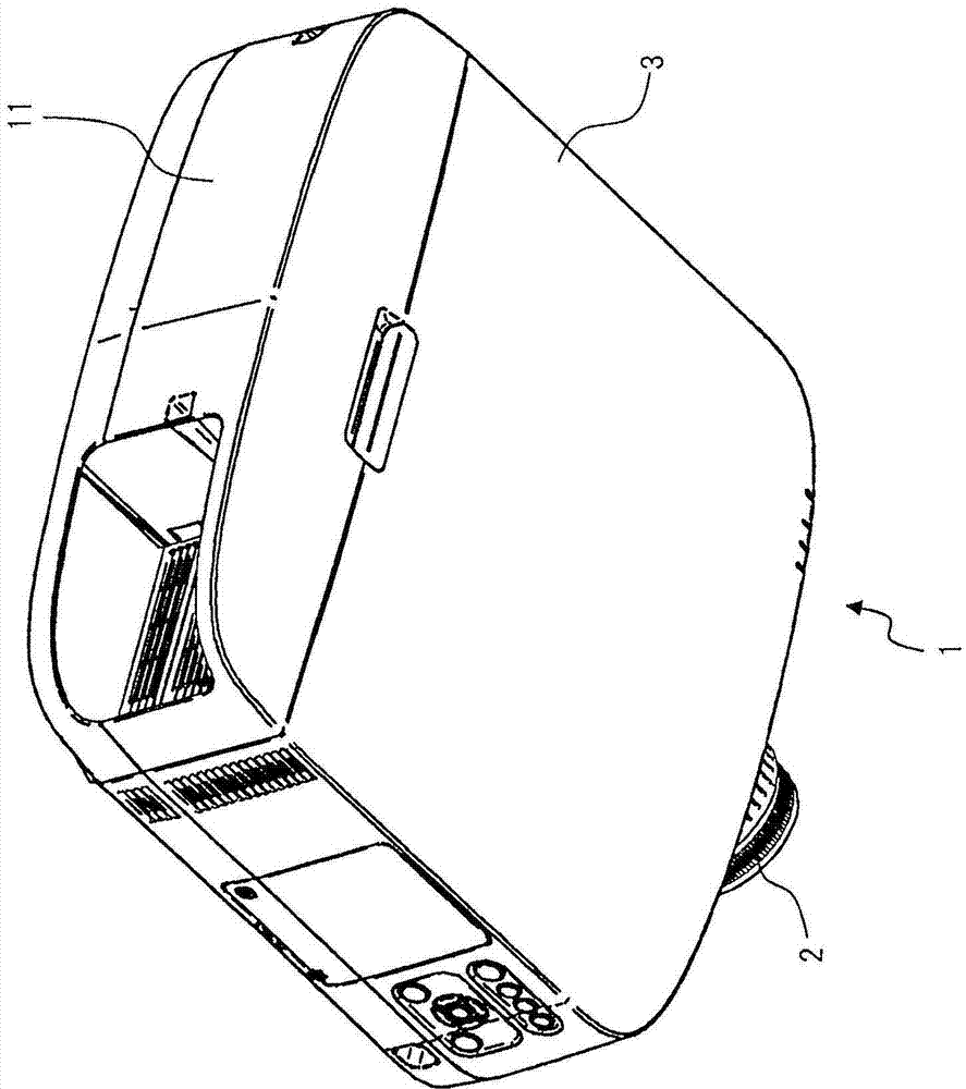
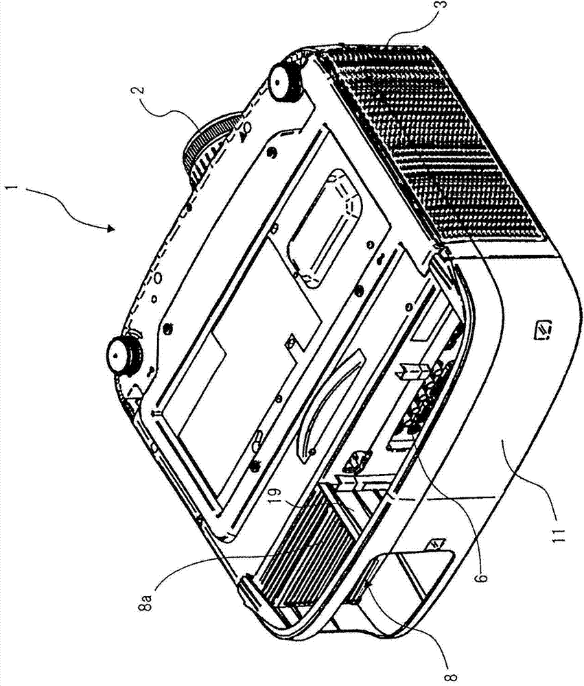
[0034] figure 1 It shows the perspective view which looked at the projection type display apparatus of embodiment from the front side downward. figure 2 It shows the perspective view which looked at the projection type display apparatus of embodiment from the downward side of the back side. image 3 It shows the perspective view which looked at the projection type display apparatus of embodiment from the upper side of a back side. Figure 4 It is a perspective view showing a state where the connector cover is removed from the rear side of the projection display device according to the embodiment. In addition, in the following description, a case will be described where the above and below refer to a projection display device installed on a ceiling as a reference, and the upper surface of the casing of the projection display device is installed in parallel wi...


PUM


Abstract

This electronic apparatus is provided with: a housing (3), which has a connecting terminal section (6) that is provided on a side surface, and engaging holes (21) that are provided in the upper surface; and a connector cover (11), which has an opening (13) for leading out, toward the outside, a cable (7) connected to the connecting terminal section (6), and engaging pins (16) that are engaged with the engaging holes (21) in the housing (3) by being inserted / extracted in the direction orthogonally intersecting the upper surface, and which covers the connecting terminal section (6).

Description

technical field [0001] The present invention relates to an electronic device including a cover member covering a connection portion between a connection terminal portion of a housing and a cable. Background technique [0002] As an electronic device such as a projection display device, a connection terminal portion is provided on a side surface of the casing. The projection display device is used by connecting the connection terminal of the connection terminal unit to the output terminal of the personal computer and the video playback device through a cable. [0003] Such a projection display device is sometimes installed in a ceiling-mounted state with the upper surface side of the housing placed on a horizontal plane facing vertically downward and the lower surface side of the housing facing vertically upward. When the projection display device is installed in a ceiling-mounted state, a plurality of cables connected to the connection terminals of the connection terminal p...

Claims


Application Information

Patent Timeline
Patent Type & Authority Patents(China)
IPC IPC(8): G03B21/14
CPCG03B21/145
Inventor 山田高久伊藤泰史井上和也
Owner NEC DISPLAY SOLUTIONS LTD
Why Eureka
Try Eureka