Polishing grinding disc for restraining full-band error of optical surface

A technology for polishing grinding discs and optical surfaces, which is applied to optical surface grinders, grinding/polishing equipment, grinding machines, etc., can solve problems such as complex finite element analysis, limited wide application, and cumbersome optical components, so as to increase the amount of grinding removal, Eliminate the effect of rotation conduction and influence

Inactive Publication Date: 2013-09-18
INST OF OPTICS & ELECTRONICS - CHINESE ACAD OF SCI
View PDF4 Cites 8 Cited by
  • Summary
  • Abstract
  • Description
  • Claims
  • Application Information

AI Technical Summary

Problems solved by technology

However, the development of passive semi-rigid grinding discs requires cumbersome and complicated finite element analysis for optical elements with specific surface shapes. The actual smoothness of the grinding discs needs to be verified and calibrated before use, which limits its wide application.

Method used


Image

  • Polishing grinding disc for restraining full-band error of optical surface
  • Polishing grinding disc for restraining full-band error of optical surface
  • Polishing grinding disc for restraining full-band error of optical surface

Examples


Embodiment Construction

[0032] The present invention will be further described below in conjunction with the accompanying drawings.

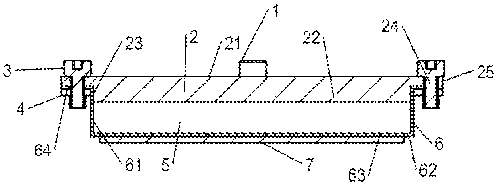
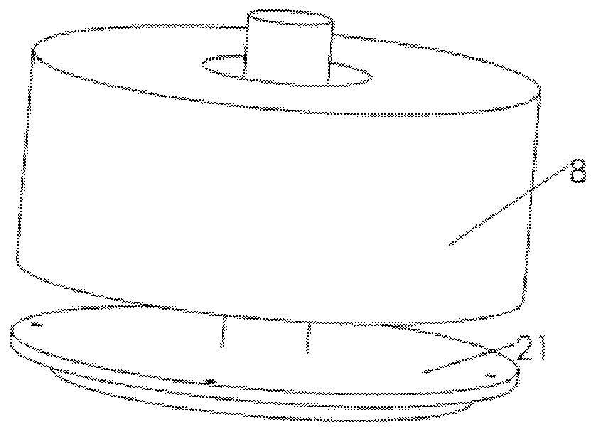
[0033] refer to figure 1 , a polishing disc for suppressing the full-frequency error of the optical surface, comprising a shaft connection end 1, a base 2, a bolt 3, a flange ring 4, a magnetorheological plasticine 5, a diaphragm sealing diaphragm 6, a polishing layer 7, and a magnetic field generator 8; where:

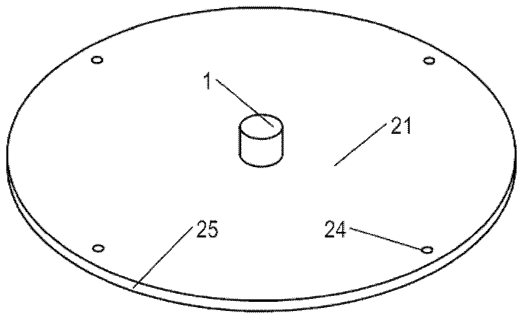
[0034] The connecting end 1 of the rotating shaft is located at the center of the outer upper part 21 of the base, and is used to connect the power output rotating shaft of the machine tool to obtain the driving force to drive the entire polishing disc of the present invention to rotate;

[0035] The base 2 is a cylinder with an outer upper part 21, an outer lower part 22, a side wall 23, a fixed screw hole 24 and an annular boss 25; the annular boss 25 is located outside the side wall 23, and the annular boss 25 has a set of Connect the screw holes 24, and ...


PUM


Abstract

The invention relates to a polishing grinding disc for restraining a full-band error of an optical surface. The polishing grinding disc is provided with a rotating shaft connecting end, a base, a flange ring, a diaphragm seal membrane, magnetorheological plasticine, a polishing pad, and a magnetic field generator, wherein the rotating shaft connecting end is located in a central position of an external upper part of the base; the base is provided with an annular boss; the annular boss is located on the outer side of a side wall; a group of fixedly connected screw holes are formed in the annular boss, and are centrosymmetric to the rotating shaft connecting end; the flange ring is an annular cylinder and is provided with a group of fixedly connected screw holes; the diaphragm seal membrane is in a bucket-shaped structure with the upper end opened; the magnetorheological plasticine is placed in a seal cavity formed by an inner wall and an upper surface of the diaphragm seal membrane as well as the bottom of the base; a boss of the diaphragm seal is fixedly connected with the annular boss of the base by the flange ring and bolts; the polishing pad is fixedly connected with a lower surface of the diaphragm seal membrane; and the magnetic field generator is placed on the upper surface of the external upper part of the base outside the grinding disc, controls magnetic field distribution in the seal cavity, generates a magnetic field parallel to a direction of a rotating shaft, and adjusts and controls a storage modulus and a loss modulus of the magnetorheological plasticine.

Description

technical field [0001] The invention belongs to the field of advanced optical manufacturing, and in particular relates to a polishing disc for suppressing errors in the full frequency range of an optical surface. Background technique [0002] Since the 1960s, various computer-controlled surface shaping techniques (CCOS) have been proposed one after another. Due to the definite material removal and high convergence rate of CCOS, this technology has become the main processing technology for large-aperture and high-precision optical components. CCOS achieves a specific amount of material removal by controlling the dwell time of the subaperture polishing tool anywhere on the workpiece surface. Therefore, a stable and predictable material removal function plays a vital role in CCOS technology. For contact polishing, a stable removal function depends on close contact and reasonable force distribution between the polishing disc and the workpiece. Rigid grinding discs can maintai...

Claims


Application Information

Patent Timeline
Patent Type & Authority Applications(China)
IPC IPC(8): B24D18/00B24B13/00
Inventor 王佳范斌万勇建施春燕孟凯
Owner INST OF OPTICS & ELECTRONICS - CHINESE ACAD OF SCI
Why Eureka
Try Eureka