Mechanism for shaping and boxing glove

A technology of gloves and push plates, applied in the field of machinery and equipment, can solve the problems of inability to realize fully automatic assembly line operation of glove packaging and boxing, inability to reshape the glove side, unfavorable glove boxing, etc., so as to achieve large operation options and boxing High efficiency and good shaping effect

Active Publication Date: 2013-09-18
ZIBO REEBOW AUTOMATION EQUIP CO LTD
View PDF7 Cites 6 Cited by
  • Summary
  • Abstract
  • Description
  • Claims
  • Application Information

AI Technical Summary

Problems solved by technology

This patent can replace manual filling of gloves, but its disadvantage is that the side of the glove cannot be shaped. When the fluffy glove is placed in the transition box, the two sides of the glove will be lifted, and the movable cover will be closed after being compressed by a manipulator or manually. board, it is still necessary to manually insert part of the exposed gloves into the transition box, and it is impossible to realize the fully automated assembly line operation of glove packaging into the box; the gloves will still rebound after the external compression force is removed, and the gloves are still in a relatively fluffy state in the transition box , which is not conducive to putting the gloves into the box; the closed movable cover is easy to pinch the edge of the glove, causing damage to the glove

Method used


Image

  • Mechanism for shaping and boxing glove
  • Mechanism for shaping and boxing glove
  • Mechanism for shaping and boxing glove

Examples


Embodiment 1

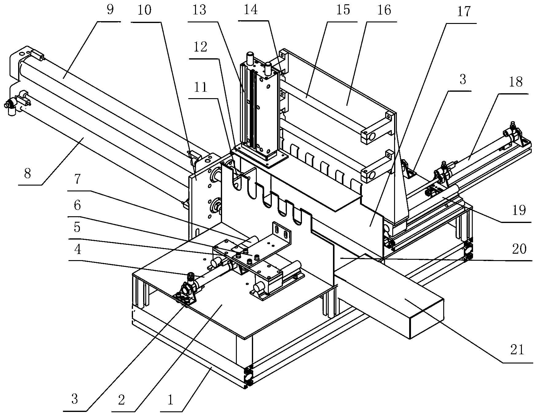
[0031] Such as figure 1 , figure 2As shown, the installation platform is fixed on the base 1, and the glove placement plate 20 is embedded in the middle of the installation platform 2, and is slidingly connected with the installation platform 2. Its cross section is U-shaped, with a groove in the middle, and both ends are flush with the installation platform 2 , the lateral compression plates 17 are arranged symmetrically on both sides of the glove placement plate 20, and the lateral compression plates 17 are movably arranged on the installation platform 2. The upper ends of the lateral compression plates 17 are provided with tooth-shaped gaps, and the upper edge is an everted arc. 17 is fixedly connected with the front end of the transverse drive cylinder 4 through the transverse top plate 6 fixedly connected with it, and the front end of the transverse drive cylinder 4 is fixed at the same time with the connecting plate 5, the connecting plate 5 is perpendicular to the axis...

Embodiment 2

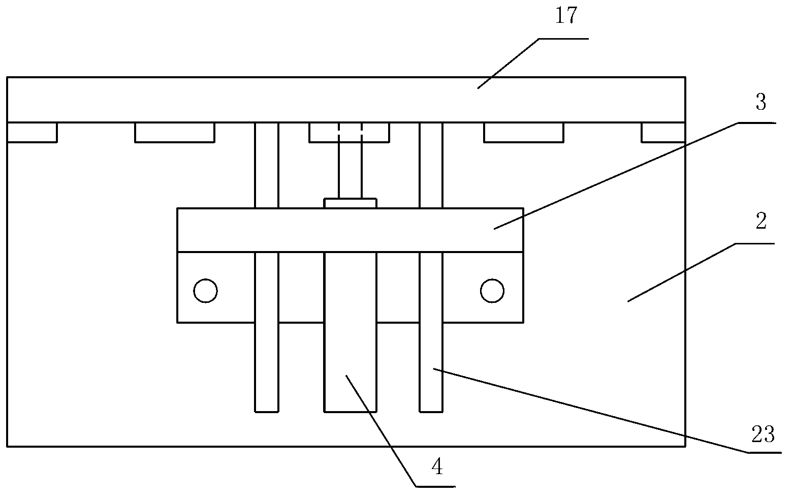
[0034] Such as image 3 As shown, the transverse compression plate 17 is fixedly connected to the front end of the transverse drive cylinder 4, the transverse drive cylinder 4 is fixed on the installation platform 2 through the mounting seat 3, and guide rods 23 are respectively arranged on both sides to make the transverse compression plate 17 move stably, and the guide rod 23 Integrated control with lateral drive cylinder.

Embodiment 3

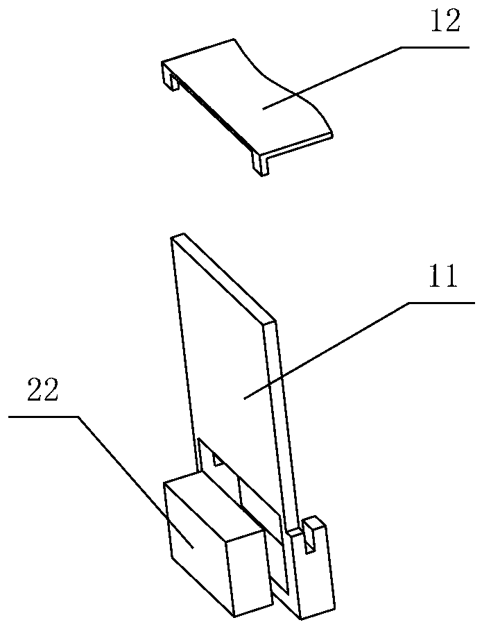
[0036] Such as Figure 4 As shown, the vertical push plate 12 is provided with a folding ear corresponding to one end of the longitudinal push plate 11, and a special-shaped hole is arranged on the fold ear. The special-shaped hole is a long hole, and one end is circular. The front end of the cylinder 9 passes through the longitudinal push plate 11 and cooperates with the shaped hole.


PUM


Abstract

The invention relates to a mechanism for shaping and boxing a plastic glove, and belongs to the field of mechanical equipment. The mechanism comprises a base, a mounting platform and a glove placing plate, wherein the glove placing plate is arranged on the mounting platform; transverse compression plates are arranged on the two sides of the glove placing plate respectively; transverse driving devices are connected with the side surfaces of the transverse compression plates; a longitudinal pushing plate is connected with one end of the glove placing plate; a boxing pushing plate is arranged on one side of the longitudinal pushing plate; the longitudinal pushing plate and the boxing pushing plate are connected with a longitudinal driving device respectively; a vertical pushing plate is arranged at the upper part of the glove placing plate, and is connected with a vertical driving cylinder; the vertical driving cylinder is arranged on a bracket in a sliding manner in the longitudinal direction; the bracket is arranged on the mounting platform. The mechanism has the advantages that automatically shaping and boxing of the glove are realized; the shaping effect is excellent; the boxing efficiency is high; the mechanism can be arranged on the glove producing and processing assembly line in a matching manner; the automatic production is realized; the labor intensity of workers are greatly reduced; the production efficiency is improved; the production cost is reduced; the mechanism facilitates the expansion of production scale of an enterprise.

Description

technical field [0001] The invention relates to a plastic glove shaping and boxing mechanism, which is especially suitable for the automatic assembly line of PVC gloves and belongs to the field of mechanical equipment. Background technique [0002] At present, the production line of plastic gloves (disposable PVC gloves) at home and abroad cannot realize the fully automated process from the glove grabbing to the box packaging. More than a hundred or so), then fall into manual operation, that is, manually stuff the gloves after coding into a packaging carton with a side opening, and then manually seal the lid at the opening. Since there is air in each glove, when dozens or hundreds of gloves are stacked together, on the one hand, the volume will be fluffy and swell, exceeding the volume of the packaging carton, and the air needs to be squeezed out manually; Its texture is soft and boneless, making it difficult to squeeze it into the packaging carton. Therefore, the manual l...

Claims


Application Information

Patent Timeline
Patent Type & Authority Applications(China)
IPC IPC(8): B65B63/00
Inventor 刘新涛潘广堂徐云海
Owner ZIBO REEBOW AUTOMATION EQUIP CO LTD
Why Eureka
Try Eureka