Electric connector

A technology of electrical connectors and connectors, which is applied in the direction of connections, circuits, parts of connection devices, etc., can solve the problems of disengagement of arm holding members, poor operability, and inability to achieve double locking, so as to prevent misinterpretation Effect

Active Publication Date: 2013-09-18
HIROSE ELECTRIC GROUP
View PDF16 Cites 5 Cited by
  • Summary
  • Abstract
  • Description
  • Claims
  • Application Information

AI Technical Summary

Problems solved by technology

[0005] However, the connector described in Patent Document 1 may inadvertently disengage the arm holding member when subjected to vibration and impact, and may not be able to realize the double locking function.
In addition, if you want to strengthen the performance against vibration and shock, you need to lock the arm holding member to fix it, and the operability may deteriorate.

Method used


Image

  • Electric connector
  • Electric connector
  • Electric connector

Examples


Embodiment Construction

[0073]In the following embodiments, for the sake of convenience, they will be divided into multiple parts or embodiments for description when necessary, but they are not irrelevant to each other unless otherwise specified, and one of them is a part of the other or All modifications, details, supplementary explanations, and other relations. In addition, in the following embodiments, when referring to the number of elements, etc. (including numbers, numerical values, amounts, ranges, etc.), except for cases where it is specifically stated or clearly limited to a specific number in principle, etc., It is not limited to the specific number, and may be more than the specific number or less than the specific number.

[0074] Hereinafter, embodiments of the present invention will be described in detail with reference to the drawings. In addition, in all the drawings for describing the embodiment, in principle, the same reference numerals are assigned to the same members, and repeate...


PUM


Abstract

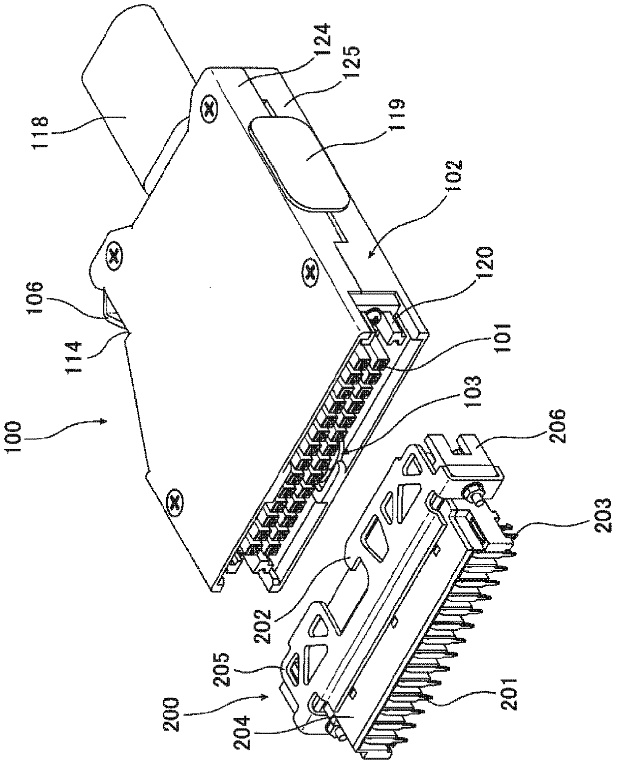
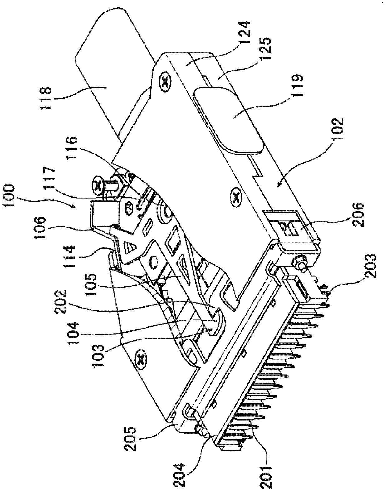
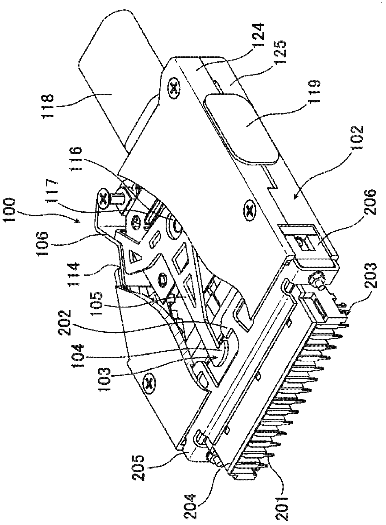
The invention provides a technology for solving a problem that an electric connector having a locking mechanism unlocks accidentally because of vibration and surge. The connector comprises a locking unit (103) for preventing the electric connector from detaching when being fitted with a side connector of an opposite side. The locking unit (103) possess a first snap part (104) snapping with a part of the side connector of the opposite side when the electric connector is fitted with the side connector of an opposite side, a main body part (105) for connecting with the first snap part (104), a first operation part (106) for connecting with the main body part (105) and performing position switch on the first snap part (104). Furthermore, a first position limitation member (107 ) (double lock) for the position that the first operation part switch to which can be selectively moved to a limited part or an unlimited part, and the limitation member (triple lock)for the position of the first position limitation part which can be selectively moved to a limited part or an unlimited part are comprised. In virtue of above arrangement, the electric connector can prevent fault unlocking.

Description

technical field [0001] The present invention relates to an electrical connector, and more particularly to an electrical connector having a lock mechanism for preventing disengagement when mated with a counterpart connector. Background technique [0002] Among electrical connectors, some electrical connectors have a locking mechanism in order to prevent disengagement when mating with a counterpart connector. In addition, some electrical connectors have a double locking function, which strengthens the locking function so that the locking mechanism will not be unintentionally unlocked due to vibration, impact, and the like. As an electrical connector having a double lock function, for example, there is a technique described in Patent Document 1 (Japanese Patent Laid-Open No. 11-26086). [0003] The connector described in Patent Document 1 is a connector using a lock arm, and when the connector is mated, the protruding piece of the lock arm engages with the protrusion of the ma...

Claims


Application Information

Patent Timeline
Patent Type & Authority Applications(China)
IPC IPC(8): H01R13/639H01R13/629
Inventor 小玉晃弘籠谷浩一
Owner HIROSE ELECTRIC GROUP
Why Eureka
Try Eureka