Leakage protection device

A leakage protection device and circuit technology, which is applied in the direction of circuit devices, emergency protection circuit devices, emergency protection devices with automatic disconnection, etc., can solve problems such as charged shells or ground wires, single functions, and personal safety hazards

Active Publication Date: 2015-11-25
HAIER GRP CORP +1
View PDF4 Cites 0 Cited by
  • Summary
  • Abstract
  • Description
  • Claims
  • Application Information

AI Technical Summary

Problems solved by technology

[0002] Existing leakage switches, circuit breakers, leakage appliances and other products have a single function, only the L-N leakage protection function, that is, when the current difference between the live wire and the neutral wire reaches a certain threshold, the power is cut off by disconnecting the live wire or the neutral wire, so that only Solve the problem of L-N leakage protection of household appliances; when the leakage current occurs in the local line, it cannot be protected or disconnected
[0003] Due to differences in regional environments, the protection function of home appliances is limited, and existing products cannot fully protect against faults.
When the following situations occur, none of them can play a protective role, and there is a great danger to personal safety:
[0004] 1. When the ground wire of the user's home system is poorly grounded, the leakage of other household appliances leads to the electrification of the shell or ground wire of the electrical equipment;
[0005] 2. When the ground wire of the user's community system is poorly grounded, the ground wire of other users' homes is charged, which leads to the electrification of the shell or ground wire of the electrical equipment;
[0006] 3. The live wire and ground wire of the user's home socket are reversed, causing the shell or ground wire of the electrical equipment to be charged

Method used


Image

  • Leakage protection device
  • Leakage protection device
  • Leakage protection device

Examples


Embodiment Construction

[0033] The present invention will be described in detail below in conjunction with the accompanying drawings and embodiments.

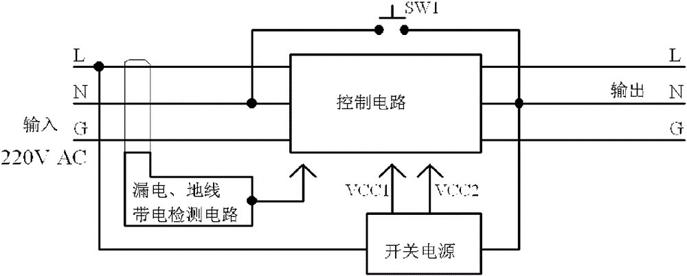
[0034] Such as figure 1 As shown, this embodiment describes a leakage protection device, including:

[0035] The detection circuit is used to detect the abnormality of the live wire L, the neutral wire N and the ground wire G in the system circuit, and output the detection result to the control circuit;

[0036] The control circuit is located at the power input end of the system circuit (located at figure 1 The left end of the third line, connected to the 220V public grid) and the power output terminal (located at figure 1 Between the right end of the middle three wires (connected with household electrical appliances), according to the circuit detection results sent by the detection circuit, the on-off of the live wire L, the neutral wire N and the ground wire G in the system circuit are controlled;

[0037] A switching power supply, connected betw...


PUM


Abstract

The invention discloses an electric leakage protection device. The electric leakage protection device comprises a detection circuit, a control circuit, a switching power supply and a control switch. The detection circuit is used for detecting abnormalities of a live wire, a neutral wire and a ground wire in a system circuit and outputting a detection result to the control circuit; the control circuit is arranged between a power input end and a power output end of the system circuit and is used for controlling on / off of the live wire, the neutral wire and the ground wire in the system circuit according to the circuit detection result sent by the detection circuit; the switching power supply is connected between the live wire and the neutral wire of the circuit and is used for providing power for the control circuit; and one end of the control switch is connected, between the power input end and the control circuit, to the neutral wire, and the other end of the control switch is connected, between the power output end and the control circuit, to the neutral wire, wherein a portion, connected with the live wire, of the switching power supply is located between the control circuit and the power input end, and a portion, connected with the neutral wire, of the switching power supply is located between the control circuit and the power output end. With the electric leakage protection device, comprehensive protection on earth leakage of the live wire and the neutral wire and on ground wire electrification can be carried out.

Description

technical field [0001] The invention relates to the technical field of electrical appliances, in particular to a leakage protection device. Background technique [0002] Existing leakage switches, circuit breakers, leakage appliances and other products have a single function, only the L-N leakage protection function, that is, when the current difference between the live wire and the neutral wire reaches a certain threshold, the power is cut off by disconnecting the live wire or the neutral wire, so that only The problem of L-N leakage protection of household appliances is solved; when the leakage current occurs in the local line, it cannot be protected or disconnected. [0003] Due to the differences in regional environment, etc., the protection function of the home appliance itself is limited, and the existing products cannot fully realize the protection against the faults that occur. When the following situations occur, none of them can play a protective role, and there i...

Claims


Application Information

Patent Timeline
Patent Type & Authority Patents(China)
IPC IPC(8): H02H3/32
Inventor 孙书波范纪青董金胜
Owner HAIER GRP CORP
Why Eureka
Try Eureka